
Capacitor with charge time reducing additives and work function modifiers

Active Publication Date: 2019-02-12
KEMET ELECTRONICS
View PDF12 Cites 1 Cited by
  • Summary
  • Abstract
  • Description
  • Claims
  • Application Information

AI Technical Summary

Benefits of technology

This patent is about improving the way solid electrolytic capacitors are made. The invention aims to make the cathode more reliable and to reduce the time it takes to charge. The method involves adding layers to the capacitor that modify the work function, which is the energy needed to transfer electrical current. Additionally, the invention includes using materials that reduce the work function. These improvements can lead to faster and more effective solid electrolytic capacitors.

Problems solved by technology

In practice, the total charge required by certain capacitors often exceeds this theoretical prediction.
Practical consequences of this anomalous charging behavior are that the charging current (dQ / dt) does not fall to low values as quickly as predicted by theory resulting in a slow charging effect.
This behavior affects measurement of DC leakage current and requires longer times to reach the specified leakage current which can affect capacitor performance in customers' circuits since when DC leakage current is measured, it takes longer than expected for the capacitor's current to fall to levels lower than the specified leakage current for the given application.
In spite of the efforts of those of skill in the art it has not been previously realized that the charge time in a capacitor is related to the inherent work function of the conductive polymer layer itself instead of PSS mobility or delamination thereby clarifying the insufficient results from previous efforts.

Method used


Image

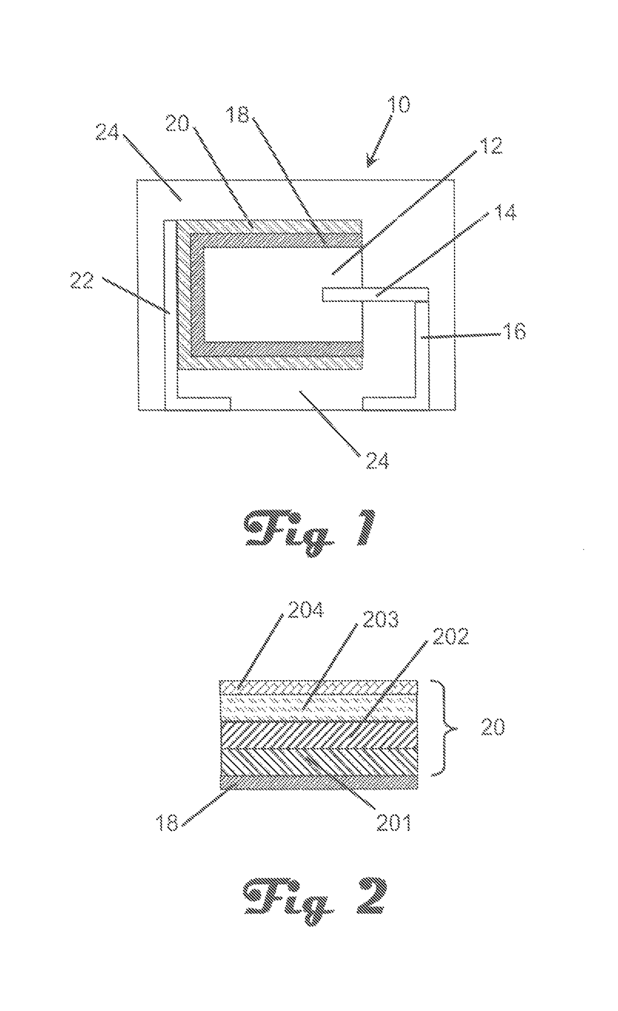
  • Capacitor with charge time reducing additives and work function modifiers
  • Capacitor with charge time reducing additives and work function modifiers
  • Capacitor with charge time reducing additives and work function modifiers

Examples


##ventive example 1

Inventive Example 1

[0072]Parts were prepared in the same manner as in Comparative Example 1 except that the decanediamine toluenesulfonate layer was replaced with zinc oxide dispersion. Alternating layers of 40 nm zinc oxide dispersion and dispersion (Clevios KV2) were applied and repeated 3 more times. The treatment and testing was the same as Comparative Example 1.

##ventive example 2

Inventive Example 2

[0073]Parts were prepared in the same manner as in Inventive Example 1 except alternating layers of cerium oxide dispersion were used instead of zinc oxide. The treatment and testing was then the same as Comparative Example 1.

[0074]

TABLE 1ExamplesCharging time (sec)Comparative example 17× theoreticalInventive Example 11× theoreticalInventive Example 21.3× theoretical

##ventive example 3

Inventive Example 3

[0075]Parts were prepared in the same manner as in Inventive Example 1 except a zinc oxide dispersion was applied before the first conductive polymer dispersion followed by alternating layers of decane diamine toluene sulfonate and conductive polymer dispersion (Clevios KV2). The treatment and testing was then the same as Comparative Example 1.


PUM


Abstract

A capacitor, and method for making the capacitor, is provided with improved charging characteristics. The capacitor has an anode, a cathode comprising a conductive polymer layer and a work function modifier layer adjacent the conductive polymer layer and a dielectric layer between the anode and the cathode.

Description

CROSS-REFERENCE TO RELATED APPLICATIONS[0001]The present invention is a divisional application of pending U.S. patent application Ser. No. 14 / 717,414, filed May 20, 2015, which in turn claims priority to U.S. Provisional Application No. 62 / 001,165 filed May 21, 2014, all of which are incorporated herein by reference.BACKGROUND[0002]The present invention is related to an improved method of preparing a solid electrolyte capacitor and an improved capacitor formed thereby. More specifically, the present invention is related to improving the charging time of a capacitor by incorporating work function modifiers in the interfaces between the dielectric and the conductive polymer layer and between adjacent conductive polymer layers.[0003]Solid electrolytic capacitors are widely used throughout the electronics industry. Conductive polymers are widely used in capacitors, solar cells and LED displays with exemplary conductive polymers including polypyrrole, polythiophene and polyaniline. Among...

Claims


Application Information

Patent Timeline
IPC IPC(8): H01G9/00H01G9/042H01G9/15H01G9/025
CPCH01G9/0036H01G9/0032H01G9/15H01G9/042H01G9/025H01G9/028H01G9/0425
Inventor CHACKO, ANTONY P.SHI, YARURAMSBOTTOM, ROBERTKINARD, JOHN T.OLS, JOHN JOSEPH
Owner KEMET ELECTRONICS
Learn More