
Layer 4 switching for persistent connections

Active Publication Date: 2019-01-29
AKAMAI TECH INC
View PDF6 Cites 1 Cited by
  • Summary
  • Abstract
  • Description
  • Claims
  • Application Information

AI Technical Summary

Benefits of technology

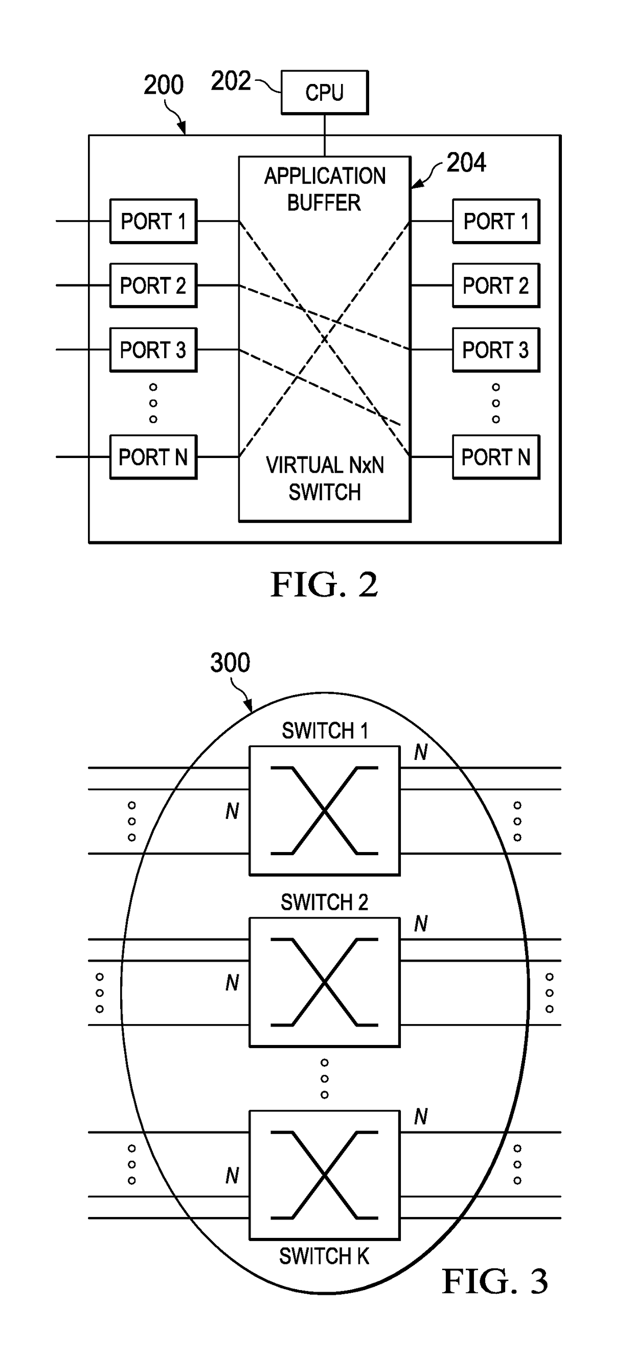
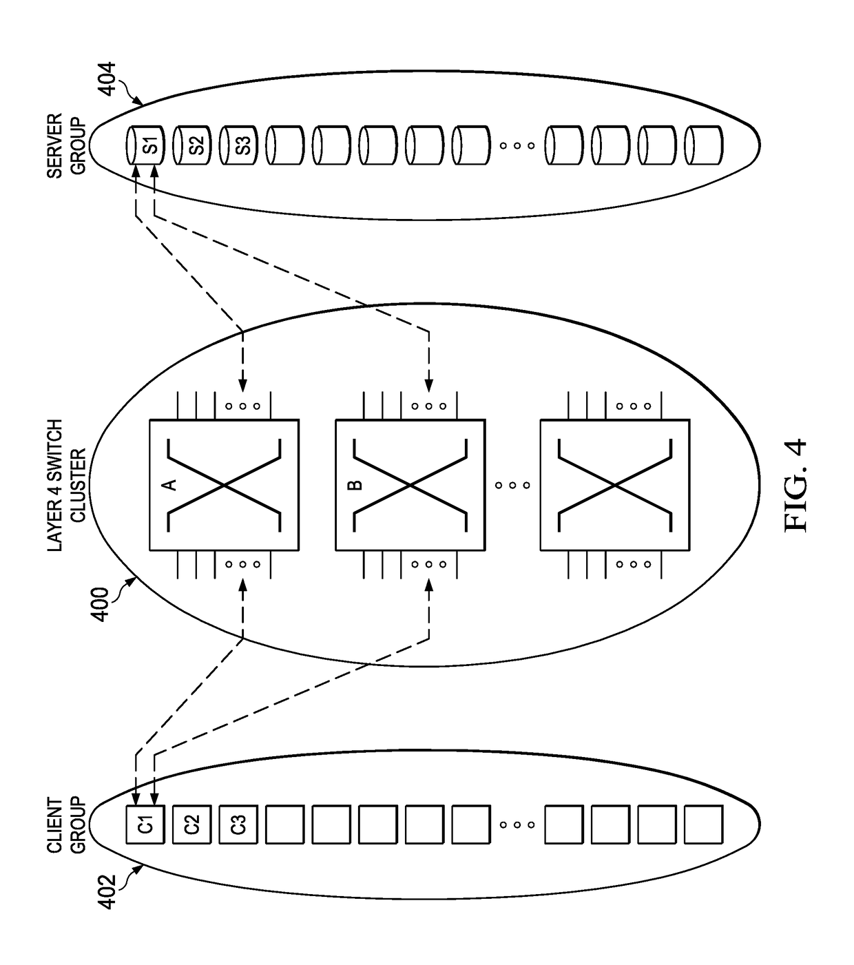
The disclosure proposes a Layer 4 switching approach that allows a set of L4 switches to act as a single "big" L4 switch. The connections between the L4 switches are carried out using Layer 2 switches. An intra-cluster routing entity of the switch maintains mapping information about the connections that have been established by the individual switches within the cluster. This approach simplifies the process of connecting multiple host ports to multiple destinations, as each host acts like a group of ports of the larger "big" switch. The intra-cluster routing entity maintains the information about which hosts and its ports are connected to which destinations, and the connections are re-used as necessary, even if one side of the "big" switch ceased using the connections. The technical effects of this approach include improved efficiency, reliability, and cost-effectiveness.

Problems solved by technology

While it is believed that one single multiplexed connection generally shows improved performance over non-multiplexed multiple connections, one drawback of such multiplexed connections is reported higher sensitivity to packet loss.

Method used


Image

  • Layer 4 switching for persistent connections
  • Layer 4 switching for persistent connections
  • Layer 4 switching for persistent connections

Examples


Embodiment Construction

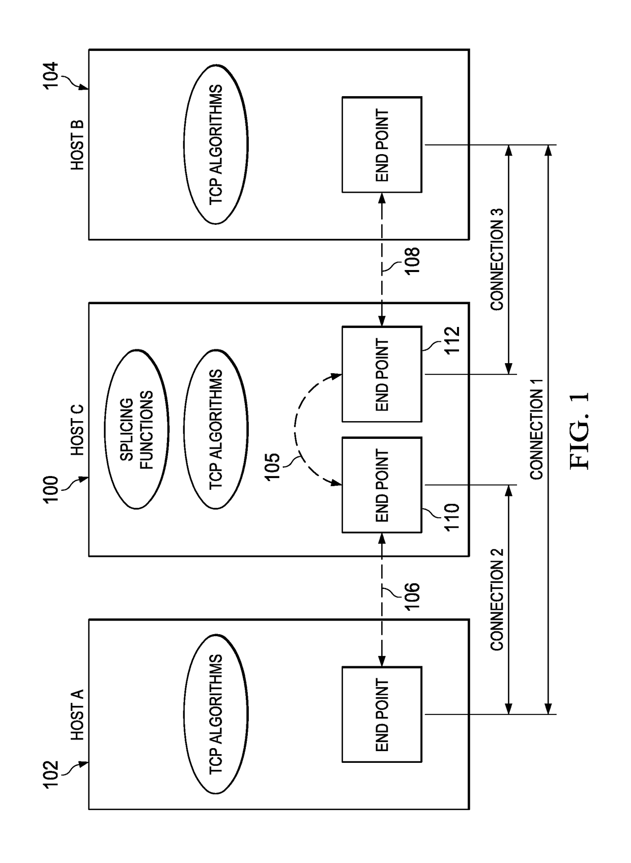
[0014]FIG. 1 depicts a model of the common implementation of a transport layer switch operating environment. In this drawing, Host C 100 is the switch between Host A 102 and B 104. More specifically, a splicing function in Host C is the switch between the two connections, one connection 106 between Host A and C, and another connection 108 between Host C and B. The splicing functionality 105 acts with respect to TCP end point 110 and 112 at Host C to seamlessly connect (splice) TCP(a,c) and TCP(c,b). The splicing functionality 105 transfers packets from one end point to another in the same host. Each packet flow, sometimes referred to as a connection segment, is terminated before being transferred to some other flow (connection). Host C is not necessarily just a single computing machine; indeed, the basic switching notion shown in FIG. 1 may be generalized as a distributed environment wherein an application layer overlay (comprising a large number of separate machines) on top of the ...


PUM


Abstract

This disclosure provides for a Layer 4 switching approach wherein a set of L4 switches are organized into a cluster so as to act as a single (or “big”) Layer 4 switch. Connections between the L4 switches are carried out, e.g., using Layer 2 switches. To this end, an intra-cluster routing entity of the switch maintains mapping information (e.g., in a database, or set of data structures) about connections that have been established by the individual switches within the cluster. In this approach, each host (itself a switch) preferably acts like a group of ports of the larger (big) switch. This obviates having each member host from having to maintain connections to many possible destinations. Rather, the intra-cluster routing entity maintains the information about which hosts (and its ports) are connected to which destinations, and the connections are re-used as necessary, even if connections on one side of the “big” switch ceased being used.

Description

BACKGROUNDTechnical Field[0001]This application relates generally to data packet switching.Brief Description of the Related Art[0002]Transport layer switches splice two OSI Layer 4 (L4) connections. Given two connection legs, Layer 4 switches typically terminate data flow of one leg first, and then forward in-sequence packets to the other leg. The isolation of packet loss in one leg from the other is an important factor in improving an overall end-to-end delivery performance because the recovery in one leg is usually quicker than otherwise in one longer connection. Multiplexed connections have multiple streams in such a connection. Layer 4 switches, without knowing the streams are multiplexed, do the same switching functions; they forward only in-sequence packets to the other leg. While it is believed that one single multiplexed connection generally shows improved performance over non-multiplexed multiple connections, one drawback of such multiplexed connections is reported higher s...

Claims


Application Information

Patent Timeline
IPC IPC(8): G06F15/173H04L29/08H04L29/12H04L12/26
CPCH04L43/0876H04L69/326H04L61/1517H04L61/4517
Inventor CHOI, BYUNG K.
Owner AKAMAI TECH INC
Learn More