
Multi-channel system for truck and cargo scanning using impulse radiation sources

a technology of impulse radiation source and scanning system, which is applied in the field of scanning system, can solve the problems of image quality degradation and image quality degradation, and achieve the effects of reducing the bandwidth of the photodiode, reducing the influence of the capacitance of the photodiode on system noise, and increasing the signal-to-noise ratio of the system

Active Publication Date: 2019-01-29
ADANI SYST INC
View PDF4 Cites 0 Cited by
  • Summary
  • Abstract
  • Description
  • Claims
  • Application Information

AI Technical Summary

Benefits of technology

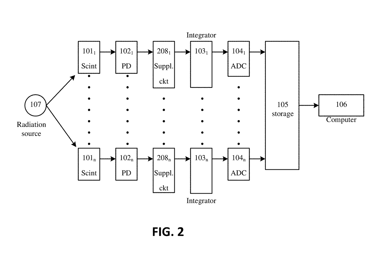
This patent describes a system for scanning trucks using multiple detection circuits. Each circuit has a scintillator, photodiode, supplemental circuit, integrator and analog-to-digital converter (ADC) connected in series. The supplemental circuit filters out low-frequency signals, amplifies the signal from the photodiode and reduces the influence of capacitance and temperature changes on the quality of the scanned truck image. The computer converts the outputs of the ADCs to a shadow image of the scanned truck. The technical effect of this system is to improve the signal-to-noise ratio, reduce system noise and improve the quality of the scanned truck image.

Problems solved by technology

Nevertheless, such conventional systems have the following drawbacks:
In order to improve sensitivity, photodiode area has to be increased accordingly, which results in increased capacitance, up to thousands pF (photodiode PIN-44DI by OSI Optoelectronics), while individual photodiode capacitance may vary, all of which deteriorates image quality.
Temperature fluctuations cause major changes in photodiode reverse current resulting in shifting of output code baselines, which also deteriorates image quality.

Method used


Image

  • Multi-channel system for truck and cargo scanning using impulse radiation sources
  • Multi-channel system for truck and cargo scanning using impulse radiation sources
  • Multi-channel system for truck and cargo scanning using impulse radiation sources

Examples


Embodiment Construction

[0021]Reference will now be made in detail to the preferred embodiments of the present invention, examples of which are illustrated in the accompanying drawings.

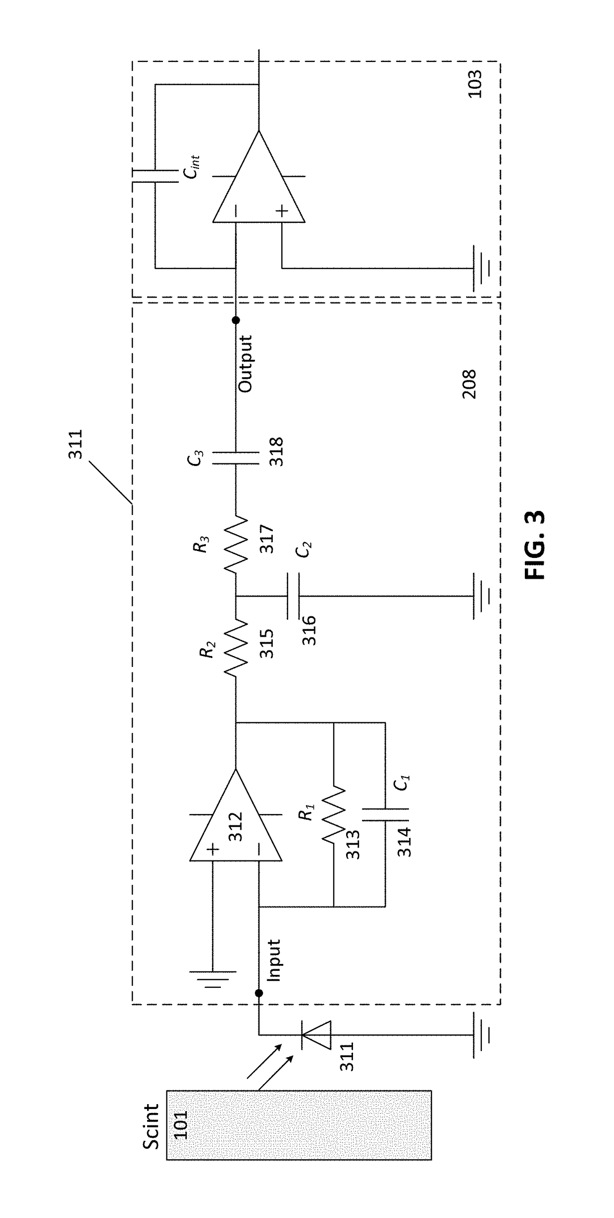
[0022]To overcome these drawbacks, a supplemental circuit is installed between the photodiodes and integrators, the circuit comprising a low-noise operational amplifier with a low bias voltage of 50-100 μV and a bias current of 1-10 pA, along with a high and low frequency filter. Also, the amplifier's non-inverting input is connected to a common bus, while its inverting input is connected to a photodiode.

[0023]Between the amplifier's output and its inverting input, there is a high-value first resistor (around several MΩ) shunted with a smaller capacitance (about 15-30 pF). The amplifier's output is connected to the integrator's input, via second and third resistors and a blocking capacitor connected in series, while the connection point between the second and third resistors is connected to the circuit's common bus, via a se...


PUM

PropertyMeasurementUnit
bias currentaaaaaaaaaa
bias voltageaaaaaaaaaa

Abstract

A multi-channel system for truck scanning, includes an impulse radiation source; and a plurality of detection circuits, each detection circuit comprising a scintillator, a photodiode, a supplemental circuit, an integrator and an ADC, connected in series. A current of the photodiode is proportional to radiation from the impulse radiation source. A data storage device stores outputs of the ADCs and provides the outputs to a computer that converts them to a shadow image of the scanned truck. The supplemental circuit isolates a capacitance of the photodiode from the integrator, filters out low frequency signals from the photodiode, amplifies the signal from the photodiode and reduces a bandwidth of the photodiode seen by the integrator. The supplemental circuit reduces an influence of capacitance of the photodiode on system noise, increases a signal-to-noise ratio of the system, and reduces an influence of photodiode temperature changes on a quality of the scanned image.

Description

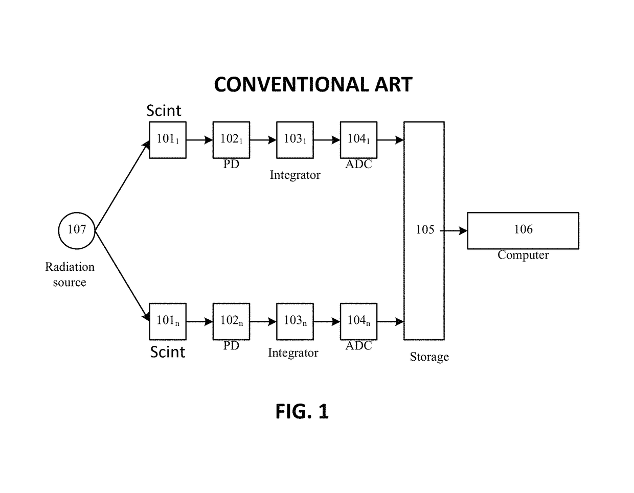
BACKGROUND OF THE INVENTIONField of the Invention[0001]The invention relates to scanning systems, and, more particularly, to a system for truck and cargo scanning that uses multiple photodetectors with increased sensitivity and improved noise resistance.Description of the Related Art[0002]A conventional multi-channel system for truck scanning comprises multiple lines of scintillators coupled with photodiodes, where the current of the photodiodes is proportional to a quantum of impulse gamma radiation they are exposed to. The radiation is generated by a radiation source—a betatron. The photodiode current flows to corresponding integrators that convert it to voltage, which, in turn, is converted to a digital value, proportional to the current, by analog-to-digital converters (ADCs). Then, a code containing these numbers is transferred to a data storage device (such as local memory or a register) and further to a computer, so that the computer displays a shadow image of the scanned obj...

Claims


Application Information

Patent Timeline
Patent Type & Authority Patents(United States)
IPC IPC(8): H05G1/64G01V5/00G01T1/20G01N23/04
CPCG01T1/2018G01V5/0016G01T1/20184G01V5/22
Inventor YAMNIY, VITALIY YEVGENIEVICHLINEV, VLADIMIR NIKOLAEVICHYAMNIY, KIRILL OLEGOVICH
Owner ADANI SYST INC
Learn More