Tactile sensor and method for evaluating touch feeling

a tactile sensor and touch technology, applied in the direction of mechanical roughness/irregularity measurement, force/torque/work measurement apparatus, instruments, etc., can solve the problems of inability to design the tip shape appropriate to various measuring objects, the flexibility of design of the touch sensor is limited, and the design change cannot be easily performed. , the effect of high design flexibility

Active Publication Date: 2019-01-29
KAGAWA UNIVERSITY
View PDF20 Cites 3 Cited by
  • Summary
  • Abstract
  • Description
  • Claims
  • Application Information

AI Technical Summary

Benefits of technology

[0022]According to the first invention, since the contact is disposed in parallel to the substrate so that the tip of the contact projects from a side face of the substrate, the side face of the substrate functions as a sensing surface, and the contact coming in contact with the measuring object is displaced in a level parallel to the substrate. The sensor part can be configured widely in a planar manner along the substrate, and thus, design change can be performed easily through pattern designing and the structure has high flexibility of design. As a result, the structure allows the contact to be displaced largely and allows detection of fine ruggedness, flexibility and other features of the surface of the measuring object. Further, the contact is disposed so that the tip of the contact projects from the side face of the substrate, and thus, force applied to the measuring object can be kept substantially constant during sensing, and the stable and sustainable contact between the contact and the measuring object allows stable measurement.
[0023]According to the second invention, the first strain detection element can detect strain of the contact in the pressing direction, and the second strain detection element can detect strain of the contact in the side slippage direction. Based on the displacement in the pressing direction and / or the displacement in the side slippage direction of the contact, the measuring object can be measured in surface shape, surface roughness, frictional force, flexibility and other features.
[0024]According to the third invention, when the tactile sensor is slid while being pressed to the measuring object, the contact is displaced following ruggedness of a comparable wavelength band to a radius of the tip of the contact. Thus, the surface shape of the measuring object can be measured by selecting a wavelength band with a radius of the tip of the contact.
[0025]According to the fourth invention, since the contacting face is arranged on the frame, the frame can limit the displacement of the contact to a predetermined amount or less, which prevents the sensor part from being braked due to excessive displacement of the contact.
[0026]According to the fifth invention, since the pair of contacting faces is inclined so as to spread toward the side face of the substrate, the gap between the contacting faces and the contacted faces becomes narrower when the contact is pressed in. In accordance with the width of the narrowed gap, the displacement of the contact in the side slippage direction can be further limited, which prevents the sensor part from being braked due to excessive displacement of the contact.
[0027]According to the sixth invention, when the tactile sensor is slid while being pressed to the measuring object, the moved distance and velocity of the tactile sensor can be measured based on the cycle of ruggedness of the measuring object measured by the sensor parts.

Problems solved by technology

However, such a tactile sensor with the surface of the substrate used as a sensing surface allows little displacement due to the limitation of material properties and / or thickness of the substrate.
Further, the flexibility in designing a tip shape of a contact of a tactile sensor is limited because the contact is vertically arranged to the substrate, and thus the tip shape appropriate to various measuring objects cannot be designed.
Therefore, the problem is that such a tactile sensor is poor in detection performance with regard to fine ruggedness on the surface of a measuring object, and thus has difficulty in evaluating a fine touch feeling.
However, it is difficult for conventional tactile sensors to keep such a measuring condition.

Method used


Image

  • Tactile sensor and method for evaluating touch feeling
  • Tactile sensor and method for evaluating touch feeling
  • Tactile sensor and method for evaluating touch feeling

Examples


first embodiment

[0049]Configuration

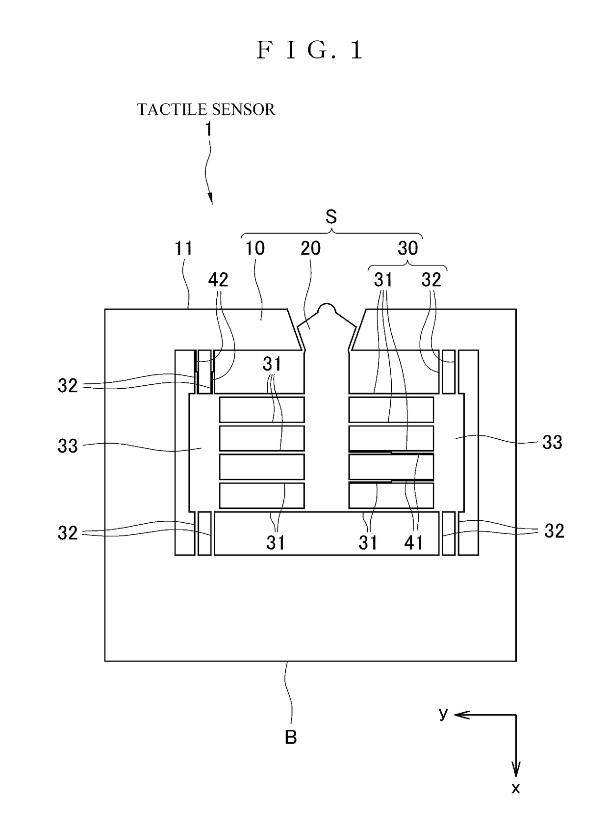
[0050]As shown in FIG. 1, a tactile sensor 1 of the first embodiment of the invention includes a sensor part S formed through working a substrate B such as a SOI substrate by semiconductor micromachining techniques. The sensor part S has a frame 10, a contact 20, and a suspension 30 that supports the contact 20 to the frame 10. The size of the sensor part S is not limited to, but several millimeters square to more than ten millimeters square.

[0051]As described below, the contact 20 and the suspension 30 are formed by etching the substrate B in a predetermined pattern so as to remove unnecessary parts thereof. The frame 10 is the remained part of the substrate B after the unnecessary parts are removed, and has a shape enclosing the contact 20 and the suspension 30. The sensor part S has a sensing surface (surface coming in contact with a measuring object) which is one side face of the substrate B. In the embodiment, the upper face out of the side faces of the subst...

second embodiment

[0090]As shown in FIG. 8, a tactile sensor 2 of the second embodiment of the invention includes two sensor parts of a sensor part S1 and a sensor part S2. Each of the sensor parts S1 and S2 has the same configuration as the sensor part S of the tactile sensor 1 of the first embodiment, and thus the same codes are attached to the same members and the description thereof is omitted herein.

[0091]The sensor parts S1 and S2 are disposed so as to share a sensing surface. That is, the contact 20 of the sensor part S1 and the contact 20 of the sensor part S2 are disposed in parallel to each other and the both tips thereof are disposed on the shared sensing surface.

[0092]The tactile sensor 2 is slid while being pressed to the measuring object O. This allows each of the sensor parts S1 and S2 to detect the surface shape of the measuring object O. The two contacts 20 of the sensor parts S1 and S2 are disposed away from each other by a predetermined distance, and thus the cycles of ruggedness o...

third embodiment

[0095]As shown in FIG. 9, a tactile sensor 3 of the third embodiment of the invention includes two sensor parts of a sensor part S3 and a sensor part S4. Each of the sensor parts S3 and S4 basically has the same configuration as the sensor S of the tactile sensor 1 of the first embodiment, and thus the same codes are attached to the same members and the description thereof is omitted herein.

[0096]As a feature of the tactile sensor 3 of the embodiment, the tips of the contact 20 of the sensor part S3 and the contact 20 of the sensor part S4 are formed in circular arcs having different radii. That is, a contact part 21 having a semicircular shape with a radius r3 is formed on the tip of the contact 20 of the sensor part S3, while a contact part 21 having a semicircular shape with a radius r4 which is smaller than the radius r3 is formed on the tip of the contact 20 of the sensor part S4. The both contacts 20 are disposed so as to project by the same projection distance v from the refe...


PUM

PropertyMeasurementUnit
central angleaaaaaaaaaa
thicknessaaaaaaaaaa
radius r4aaaaaaaaaa

Abstract

To provide a tactile sensor that allows a contact to be displaced largely and can detect fine ruggedness, flexibility, and other features of a surface of a measuring object.A sensor part S includes a frame 10 that includes a side part of a substrate B, a contact 20 that is disposed in parallel to the substrate B so that a tip of the contact 20 projects from a side face of the substrate B, a suspension 30 that supports the contact 20 to the frame 10, and displacement detectors 41 and 42 each of which detects displacement of the contact 20. The side face of the substrate B functions as a sensing surface. The contact 20 coming in contact with a measuring object O is displaced on a level parallel to the substrate B. Since the sensor part S can be configured widely in a planar manner along the substrate B, the structure has higher flexibility of design. As a result, the sensor part S allows the contact 20 to be displaced largely, and can detect fine ruggedness, flexibility and other features of the surface of the measuring object O.

Description

TECHNICAL FIELD[0001]The invention relates to a tactile sensor and a method for evaluating a touch feeling, and especially to a tactile sensor for use to quantify a touch feeling felt by a human and a method for evaluating a touch feeling based on the data acquired by the tactile sensor.BACKGROUND ART[0002]Various tactile sensors that simulate a human feeling in an engineering manner have been developed. Especially, a tactile sensor that is made by semiconductor micromachining techniques and can read a lot of sensor signals with less wiring allows a lot of sensor parts to be arranged in high density, and advantageously has high positional resolution.[0003]As the tactile sensors made by semiconductor micromachining techniques, for example, a tactile sensor that utilizes deformation of a thin silicon diaphragm (Patent Literature 1) and a tactile sensor that utilizes deformation of hinge structure (Patent Literature 2) are known. Each of these conventional tactile sensors disclosed in ...

Claims


Application Information

Patent Timeline
Patent Type & Authority Patents(United States)
IPC IPC(8): G06F11/00G01B5/28G01L5/00G01L1/18G01B7/16
CPCG01L5/0038G01L1/18G01B7/18G01B5/28
Inventor TAKAO, HIDEKUNI
Owner KAGAWA UNIVERSITY
Why Eureka
Try Eureka