
Immersion treatment installation

a technology for installation and treatment, applied in the direction of coatings, conveyor parts, transportation and packaging, etc., can solve the problems of high complexity of holding points, single kinematics, and a certain degree of apparatus expenditure, and achieve the effect of preventing jerky movements

Active Publication Date: 2019-01-15
EISENMANN GMBH
View PDF59 Cites 2 Cited by
  • Summary
  • Abstract
  • Description
  • Claims
  • Application Information

AI Technical Summary

Benefits of technology

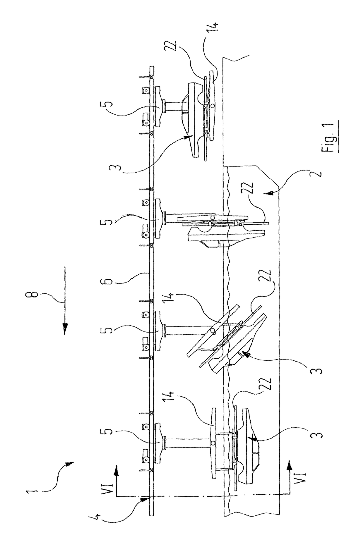
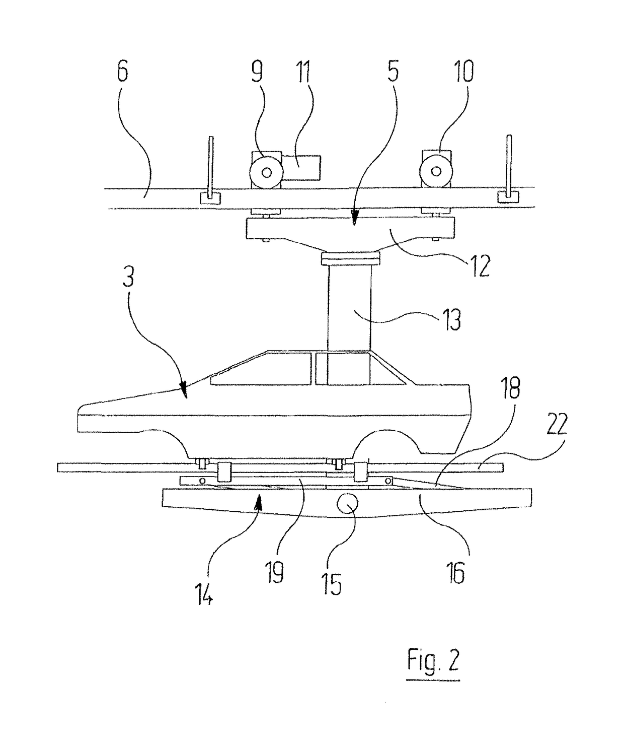
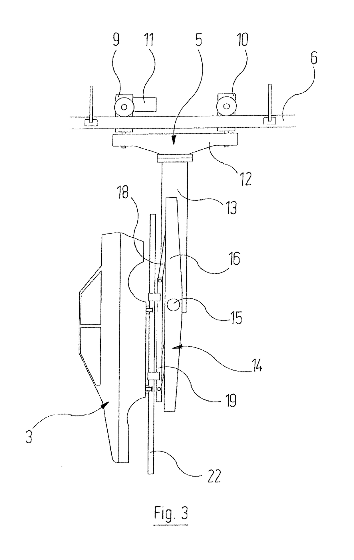
The present invention is an immersion treatment installation designed to be simpler and more economical than previous versions. It requires less expenditure on control systems. The invention also includes a mechanism that allows the object to be positioned at a maximum vertical distance from the rotation axis, which makes it more stable during treatment. The connecting structure of the installation includes at least two parallel connecting rods that are connected in articulated manner to the carrying platform and the holding structure of the object. This design ensures that the parallelogram formed by them lies flat in the non-immersed position and maximizes the spacing between the carrying platform and the holding structure when the object reaches the second position after a rotation through 180°. Damping or braking devices may be included to prevent jerky movements.

Problems solved by technology

The fundamental problem with immersion treatment installations which operate with a conveyor system which has one or more transport carriages and can essentially be operated continuously relates to how the object to be treated can be lowered from the transport position, in which it is at a height above the level of the treatment fluid, so that it is fully immersed in the treatment fluid.
In the case of objects which are very heavy, this requires highly complex holding points due to the very high forces produced.
Moreover, only single kinematics are possible during the immersion and removal of the objects.
Nevertheless, it involves a certain degree of expenditure on apparatus.

Method used


Image

  • Immersion treatment installation
  • Immersion treatment installation
  • Immersion treatment installation

Examples


Embodiment Construction

[0029]While this invention is susceptible of embodiment in many different forms, there is shown in the drawings and will herein be described in detail one or more embodiments with the understanding that the present disclosure is to be considered as an exemplification of the principles of the invention and is not intended to limit the invention to the embodiments illustrated.

[0030]The cataphoretic immersion painting installation, which is denoted as a whole by the reference numeral 1 and described below with reference to the different Figures, is known in its basic structure from DE 20 2008 017 770, in particular from FIGS. 21 to 38 therein. Additional reference is made to this publication. Unless described otherwise below, the construction of the present cataphoretic immersion painting installation 1 corresponds to the known immersion painting installation. The corresponding structural features are summarised briefly as follows:

[0031]The cataphoretic immersion painting installation ...


PUM


Abstract

An immersion treatment installation, which includes at least one immersion tank in a way known per se. A conveying system brings the items to be treated up to the immersion tank, into the space inside the immersion tank, out of it and away from it. The conveying system includes at least one transporting carriage, which has a carrying platform, which is pivotable about a pivot axis and to which at least one item can be fastened with the aid of a connecting structure. This connecting structure is movable on its own to such an extent that, with increasing pivoting from the unimmersed position, the distance between the item and the pivot axis becomes increasingly greater under the influence of gravitational force.

Description

RELATED APPLICATIONS[0001]This application is a national phase of International Patent Application No. PCT / EP2013 / 000401, filed Feb. 12, 2013, which claims the filing benefit of German Patent Application No. 10 2012 003 271.4, filed Feb. 21, 2012, the contents of both of which are incorporated herein by reference.FIELD OF THE INVENTION[0002]The invention relates to an immersion treatment installation having[0003]a) at least one immersion tank, which can be filled with a treatment fluid, in particular paint, in which the objects to be treated, in particular vehicle bodies, can be immersed;[0004]b) a conveyor system, which can move the objects to be treated towards the immersion tank, into the interior of the immersion tank, out of the immersion tank and away from this and which comprises at least one transport carriage which can be moved in a translatory direction and has a carrying platform which is rotatable about an axis of rotation and to which at least one object can be fastened...

Claims


Application Information

Patent Timeline
Patent Type & Authority Patents(United States)
IPC IPC(8): B05C13/02B05C3/10B05D1/18B05C11/08B65G17/20B65G19/02B65G47/61
CPCB05C3/10B05C11/08B05C13/02B05D1/18B65G47/61B65G17/20B65G19/025B65G49/04B65G49/0413B65G2201/0294
Inventor ROBBIN, JORG
Owner EISENMANN GMBH
Learn More