
Automatic feed supplement mechanism for LED braiding machine

A braiding machine and automatic technology, applied in packaging automatic control, packaging, packaging protection, etc., can solve the problems of high man-machine ratio, no patent document of tape braiding machine image feeding mechanism, low production efficiency, etc.

Active Publication Date: 2013-12-25
SHENZHEN HI TEST SEMICON EQUIP
View PDF4 Cites 0 Cited by
  • Summary
  • Abstract
  • Description
  • Claims
  • Application Information

AI Technical Summary

Problems solved by technology

[0002] In the LED taping equipment, the LED enters the carrier tape after being tested and forward, and the final image inspection is required before the tape and coil can be sealed. In this image inspection process, side materials, reverse materials or materials are often found. Alarms and shutdowns caused by abnormal problems such as defects. Existing equipment generally eliminates alarms manually, which is highly dependent on operators
It is observed that when the quality of some materials to be edited is not very high, the error rate of image detection is still very high, which makes the operator need to repeatedly clean and replenish materials, greatly reducing the degree of automation of the equipment, low production efficiency, man-machine The ratio is high, which is a phenomenon that customers do not want to see
[0003] At present, there are no patent documents related to the video feed mechanism of the braiding machine at home and abroad

Method used


Image

  • Automatic feed supplement mechanism for LED braiding machine
  • Automatic feed supplement mechanism for LED braiding machine
  • Automatic feed supplement mechanism for LED braiding machine

Examples


Embodiment Construction

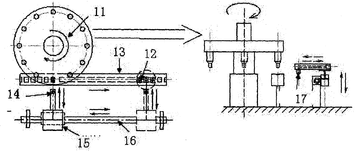
[0025] Such as figure 1 and figure 2 As shown, under normal circumstances, this part is designed to solve the discharge of defective products at the image test end and take a piece of material from the entrance of the carrier tape to replace it at this position. During the taping process, the image detection CCD detects 1 station in real time, that is, 12 materials at the image position. If any abnormalities such as reverse material, side material or broken material are found, the automatic feeding manipulator will return the "bad" material from the carrier tape. Take it out and discharge it into the accumulator, then take a piece of material from the entrance 14 of the carrier belt (2 stations) and put it back to the position of 1 station, and the manipulator returns to its position. At this time, the impact detection CCD will compare the image again, if pass, the machine will continue to weave the tape along the tape guide rail 13, otherwise repeat the above feeding proce...


PUM


Abstract

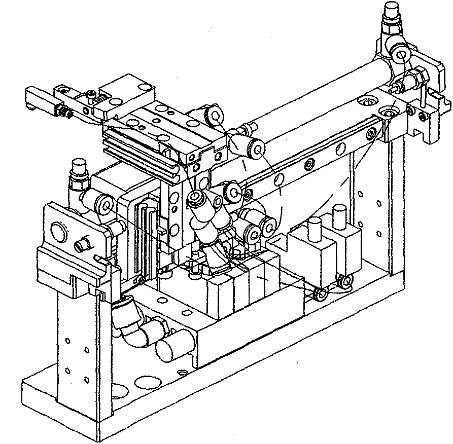
The invention relates to an automatic feed supplement mechanism for an LED braiding machine, comprising a suction head component, an executing component, a gas circuit component and a rack component, wherein the suction head component comprises a suction nozzle, a suction nozzle arm and a torsional spring; the suction nozzle is for sucking material and blowing material, and is connected with the suction nozzle arm; the gas circuit component comprises a windpipe and a control valve, wherein the windpipe and the control valve are for controlling and coordinating movements of the air cylinder and the suction nozzle; the rack component is for installing components and supporting the suction head component, the executing component and the gas circuit component; the rack is provided with a rodless cylinder and a linear guide rail; the clamping plate of the rodless cylinder is fixed on the rack pedestal to move suction arm to the left and right; the suction head is installed on a combined air cylinder which has front-back and left-right freedom degrees; the combined air cylinder is installed on the rodless air cylinder and the linear guide rail; the guide rail supports and guides the suction head to move to the left and right. The gas circuit component can control the suction nozzle for positive and negative pressure switching according to the program instruct, and can blow material into a material collector in one time, thus no additional blowing mechanism is needed.

Description

technical field [0001] The invention relates to an LED braiding machine, and further relates to an accessory of the LED braiding machine: an automatic feeding mechanism. Background technique [0002] In the LED taping equipment, the LED enters the carrier tape after being tested and forward, and the final image inspection is required before the tape and coil can be sealed. In this image inspection process, side materials, reverse materials or materials are often found. Alarms and shutdowns caused by abnormal problems such as defects. Existing equipment generally eliminates alarms manually, which is highly dependent on operators. It is observed that when the quality of some materials to be edited is not very high, the error rate of image detection is still very high, which makes the operator need to repeatedly clean and replenish materials, greatly reducing the degree of automation of the equipment, low production efficiency, man-machine The ratio is high, which is a phenome...

Claims


Application Information

Patent Timeline
Patent Type & Authority Patents(China)
IPC IPC(8): B65B15/04B65B57/14B65B35/18
Inventor 唐君强卓维煌
Owner SHENZHEN HI TEST SEMICON EQUIP
Learn More