
Self-damping shutter apparatus for exposure system of photolithography machine

a self-damping, shutter technology, applied in the direction of photomechanical equipment, instruments, cameras, etc., can solve the problems of insufficient repeatability affecting the stability of the shutter blade, lack of consistency, etc., to improve the shading effect of the exposure light, improve the opening or closing consistency, and improve the repeatability of the exposur

Active Publication Date: 2018-11-20
SHANGHAI MICRO ELECTRONICS EQUIP (GRP) CO LTD
View PDF13 Cites 0 Cited by
  • Summary
  • Abstract
  • Description
  • Claims
  • Application Information

AI Technical Summary

Benefits of technology

The present invention provides a self-damping shutter device for improving the exposure process in a photolithography tool. The device has improved consistency and repeatability, with reduced interference from the control side. The opening and closing of the shutter blades are driven by a magnetic damping braking motor, which keeps them stable without needing a current supply. This saves energy and reduces the duration of current control. The device also has excellent non-linear damping and rapid braking capabilities, improving the braking of the shutter blades.

Problems solved by technology

The control side may interfere with the exposure process, and the open-loop current control may affect the stability of the shutter blades 100 during their acceleration and braking.
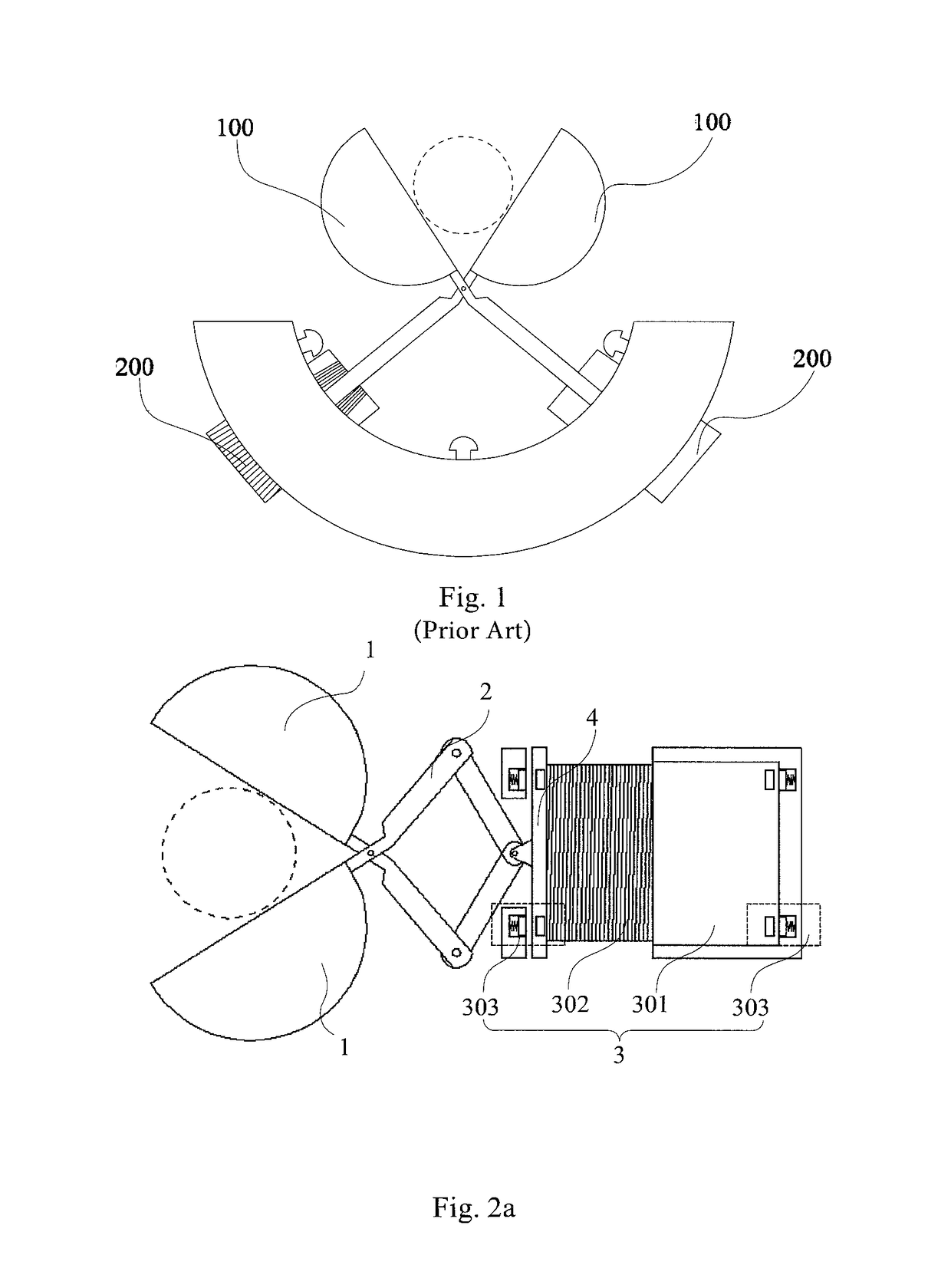
Additionally, as the shutter blades 100 are separately controlled by the respective voice coil motors 200, there is a lack of consistency between their opening or closing processes, leading to insufficient repeatability of the shutter blade 100 and impaired exposure performance.

Method used


Image

  • Self-damping shutter apparatus for exposure system of photolithography machine
  • Self-damping shutter apparatus for exposure system of photolithography machine
  • Self-damping shutter apparatus for exposure system of photolithography machine

Examples


Embodiment Construction

[0028]The present invention will be described below in detail with reference to the accompanying drawings.

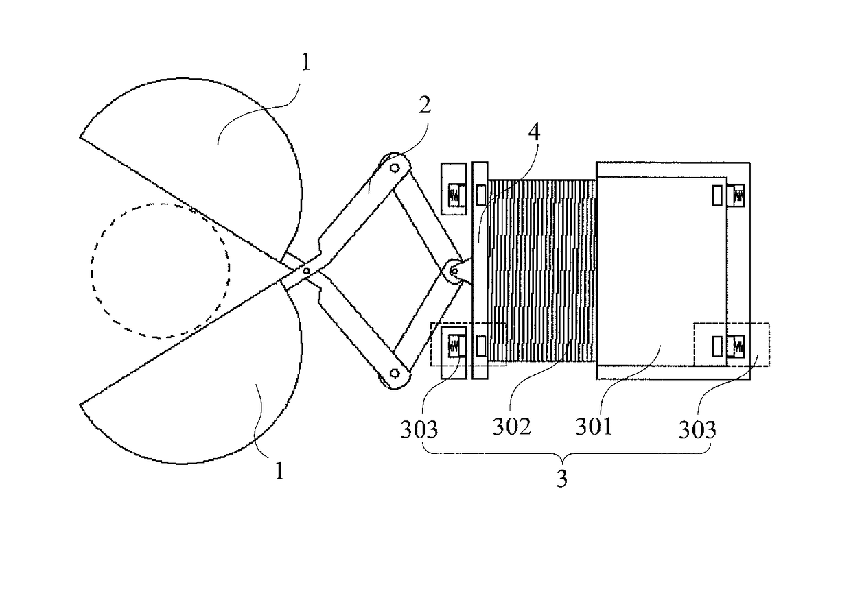
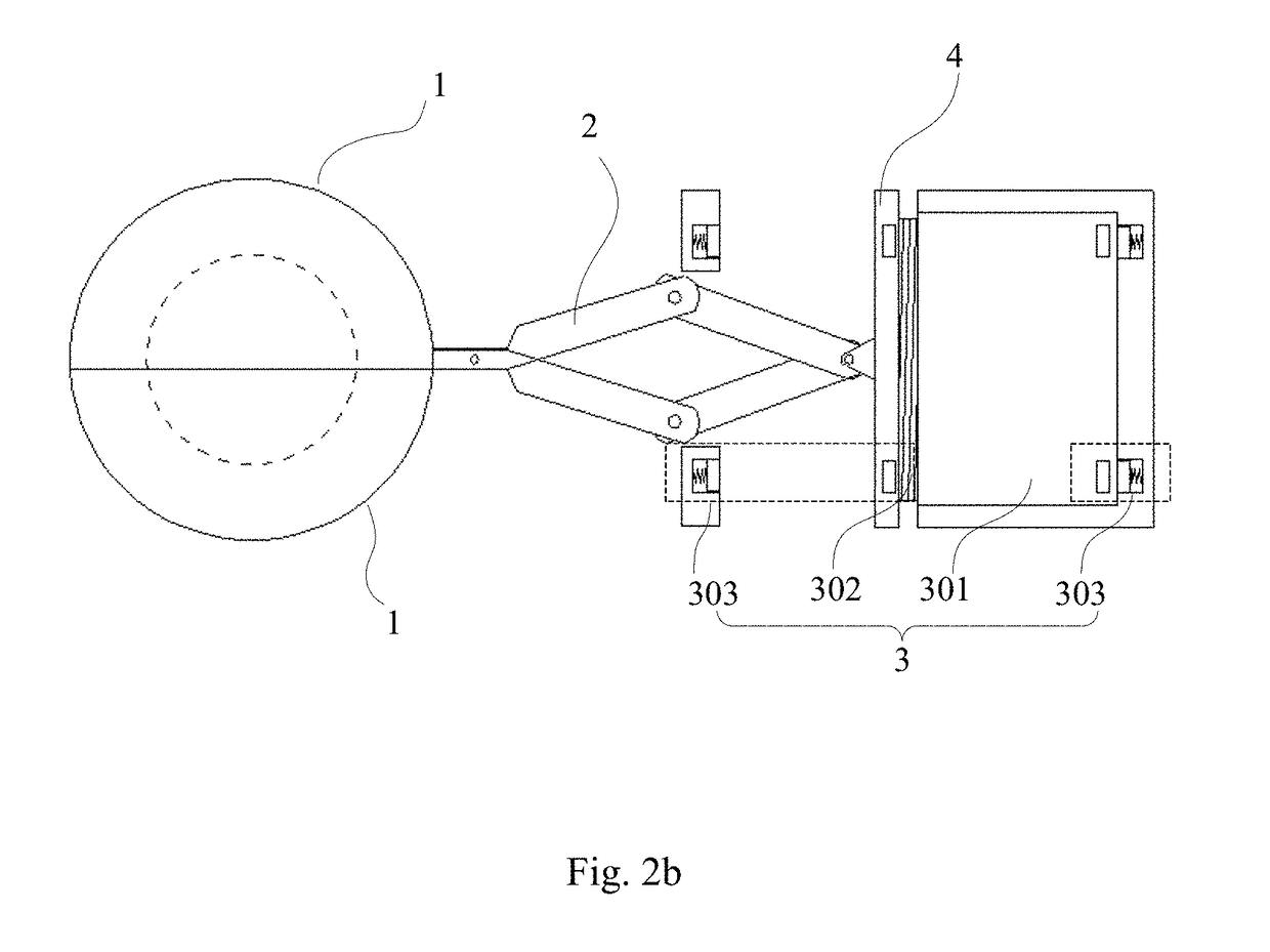
[0029]Referring to FIGS. 2a and 2b, a self-damping shutter device for use in an exposure sub-system of a photolithography tool comprises: at least two shutter blades 1, configured to shade light bound to an exposure area when they are in a closed configuration; a shutter actuation arm 2, adapted to drive the shutter blades 1 into the closed configuration or an open configuration in a synchronized manner; and a magnetic damping braking motor 3, configured to drive or brake the shutter actuation arm 2. The magnetic damping braking motor 3 drives and brakes the shutter blades 1 through the shutter actuation arm 2. Although two shutter blades 1 are depicted in FIGS. 2a and 2b, those skilled in the art will appreciate that three, four or more shutter blades 1 may also be used as long as they can shade the light bound to the exposure area when in the closed configuration.

[0030]Referri...


PUM

PropertyMeasurementUnit
temperatureaaaaaaaaaa
areaaaaaaaaaaa
speedsaaaaaaaaaa

Abstract

A self-damping shutter apparatus for use in an exposure system of a photolithography machine, comprising: at least two pieces of shutter blades (1) for cutting off light source to an exposure area when the shutter is closed; a shutter driving arm (2), for driving the shutter blades (1) to synchronically open or close; a magnetic damping brake motor (3), for driving or braking the shutter driving arm (2), and the magnetic damping brake motor (3) drives and brakes, via the shutter driving arm (2), the shutter blades (1). The self-damping shutter apparatus for use in the exposure system of the photolithography machine increases consistency of opening or closing the shutter blades, improves a light shading effect of the shutter apparatus in an exposure, and improves stability in the process of opening or closuring the shutter blades. When the shutter blades complete actions of opening or closing, current is not needed, the magnetic damping braking motor enables the shutter blades to maintain the state of opening or closing, shortens duration of control current, reduces heat dissipation, and saves energy.

Description

TECHNICAL FIELD[0001]The present invention relates to the manufacturing of photolithography equipment and, more particular, to a self-damping shutter device for use in an exposure sub-system of a photolithography tool.BACKGROUND[0002]Photolithography is a technique for printing a pattern with features onto the surface of a substrate. A commonly-used substrate is a semiconductor wafer or a glass substrate which is surface-coated with a light-sensitive material. During a photolithography process, a wafer is placed on a wafer stage and the pattern with features is projected onto the surface thereof through an exposure device incorporated in the photolithography equipment.[0003]Referring to FIG. 1, a conventional damping-free shutter device used in an exposure sub-system of a photolithography tool includes: at least two shutter blades 100 provided with respective voice coil motors 200 for driving the shutter blades 100 into an open or closed configuration. Motions of the shutter blades ...

Claims


Application Information

Patent Timeline
Patent Type & Authority Patents(United States)
IPC IPC(8): G03B9/14G03F7/20G03B9/08H01L21/027
CPCG03B9/08G03B9/14G03F7/20H01L21/027G03F7/7055G03F7/70058G03F7/70066G03F7/7015G03F7/70758
Inventor SHI, SHUOJI, HANCHUAN
Owner SHANGHAI MICRO ELECTRONICS EQUIP (GRP) CO LTD
Learn More