Firearm with locking lug bolt, and components thereof, for accurate field shooting

a technology of locking lug bolts and components, applied in the field of firearms, can solve the problems of inability to accurately accurately identify firearms, work well, and inability to accurately locate benchrest rifles in the field, and achieve the effects of improving accuracy, improving accuracy, and increasing coaxial alignmen

Active Publication Date: 2018-11-20
FOSTER RONALD ANDREW
View PDF21 Cites 4 Cited by
  • Summary
  • Abstract
  • Description
  • Claims
  • Application Information

AI Technical Summary

Benefits of technology

[0011]Components of a firearm having a bolt with locking lugs are adapted for improved accuracy. At least one adaptation in the components for improving accuracy provides increased coaxial alignment between the bolt, the cartridge, the receiver, and / or the barrel of a firearm, for example, including firearms typically considered field firearms or firearms typically considered benchrest firearms. Said at least one adaptation preferably comprises adaptation of the receiver inner surface for close tolerance / mating with the lugs while only in the locked position. The interaction of the bolt locking lugs with said receiver inner surface may provide a cleaning capability, for enhancing tolerance of the firearm action to interfering elements. Said at least one adaptation may comprise a shape / contour of the lug circumferential outer surface that enhances said cleaning capability and element tolerance. Said at least one adaptation may comprise said receiver inner surface being in a close tolerance / mating relationship with a non-threaded, axial surface of the barrel.
[0012]Coaxial alignment of the bolt and the bolt distal face in the receiver bore / boltway is accomplished in a way that prevents interference by debris, such as dirt, ice, or water, from unduly interfering with critical moving parts of the bolt. Preferably, when rotating from the unlocked to the locked position, the bolt lugs move from areas within the receiver where relatively larger spaces exist between the lugs and the receiver, to areas where relatively smaller spaces exist between the lugs and the receiver. This is preferably done by making a distal portion of the receiver bore / boltway not exactly cylindrical, for example, by forming ramps on the interior surface of the receiver lug space. When the bolt rotates into the locked (“battery”) position, the bolt lugs move from loose tolerance areas that provide room for debris accumulation, along transition areas of the ramps that clean / scrape debris from the lugs, to very tight tolerance areas of the ramps where the lugs mate with the receiver.
[0013]Further coaxial alignment of the firearm components may be accomplished by providing an extension on the barrel that mates, around at least a portion of the circumference of the barrel, with at least a portion of the inner surface of the receiver. Preferably, this is done by providing an axial, non-threaded extension that protrudes proximally beyond the threaded region of the barrel to mate with the axial, receiver inner surface with which the lugs mate when locked. Said mating of the non-threaded extension results in significantly more precise and exact coaxial alignment of the barrel bore with the receiver bore / boltway and the locked bolt, compared to the misalignment caused by the mandatory thread clearances in a threaded barrel connection.
[0014]In preferred embodiments, therefore, a single surface provides the ramps / surfaces both for mating with the bolt lugs only during lock-up, and for mating with the barrel extension. This single surface is at least a portion of the receiver inner surface forward (distal) of the lug stops and rearward (proximal) of the receiver threads. For example, when the receiver inner surface is ramped from the lug stops to the threads of the receiver, then the bolt lugs mate with proximal regions of the ramp crests, and the barrel extension mates with distal regions of the crests. Alternatively, when the receiver inner surface is ramped near the lug stops, but is another shape near the receiver threads, then the bolt lugs mate with the crests near the lug stops, and the barrel extension mates with one or more regions of, or the entire, said another shape near the receiver threads. In certain embodiments, said “another shape” may comprise, consist essentially of, or consist of, the crest surface(s) extending distally past the lugs and into the barrel-extension-receiving space, so that a barrel extension mating with said distally-extending crest surface(s) would be mating with “the same surface” with which the lugs mate in the locked position. Thus, it is preferred that troughs are provided in the receiver inner surface near the lug stops, to provide more clearance for debris entering the receiver that might otherwise interfere with the rotating bolt, but said debris-receiving troughs are not necessarily required where the installed barrel extension resides, because it does not move during operation and debris at the installed barrel is not a significant concern. Said mating with the same surface, and the distal location of said same surface in the action, simplifies and / or makes more accurate and precise, the machining step(s) for the firearm action.
[0015]Additionally or instead, certain embodiments of the bolt lugs outermost surfaces comprise axial curvature, and / or other axial non-linearity, for reducing the surface area of said outermost surfaces that mates with the receiver inner surface in the locked position. Said axial curvature or non-linearity provides at least one region of maximum lug diameter and at least one region of lug diameter that is smaller compared to said maximum lug diameter. In the case of axial curvature, each lug preferably curves in an axial direction between a single maximum lug diameter and one or more end edges that are reduced in diameter; this places the maximum lug diameter region relatively close to the receiver inner surface, and the rest of the outermost surface of each lug relatively distant from the receiver inner surface. In the case of other non-linearity, each lug may comprise ridges and recesses in said outermost surface. Thus, due to said axial curvature or other axial non-linearity, only a small surface area of the lugs mates, when the lugs are rotated to the locked position, in very tight tolerance with the minimum-diameter portions (crests) of the ramps of the receiver inner surface.
[0016]Therefore, certain embodiments align the bolt, receiver, and barrel of the firearm in a coaxial and concentric configuration by providing surfaces of tighter tolerances distal of the lug stops and close to the chamber, for mating with the locked lugs and for mating with the barrel, while providing looser tolerances for the bolt during axial travel, and prior to lock-up, to allow for satisfactory field operability. Certain of these embodiments minimize the number of separate machining steps, and minimize or eliminate the custom / hand-work, needed to build the various portions of the action and chamber, in order to provide more economical manufacture, with fewer alignment errors.

Problems solved by technology

A combination of multiple of these misalignments tends to create an inaccurate firearm, especially in field firearms that are made with loose tolerances to allow movement and cycling of the action in spite of interference by elements present in outdoor or other non-controlled / non-clean environments.
Benchrest rifles have such tight tolerances that they don't work well with dirt and weather encountered in the field and require frequent cleaning after only one or a few rounds are fired, but they are consistently more accurate.
Additionally, benchrest rifles are usually impractical in the field due to their weight.
The components of benchrest rifles are built heavier to resist flexing that causes harmonic vibrations, which can cause inaccuracy.
This compromise, however, makes the rifle action more susceptible than a field rifle to binding and blockage from outdoor interferences such as dirt and ice, and makes the rifle still not as accurate as a benchrest gun that often has approximately 0.0005 (five ten-thousandths) inch clearance.
Such bosses, however, are behind (proximal to) the bolt lugs, and are susceptible to binding and blockage when outdoor interferences such as dirt and ice enter between the bolt bosses and the receiver bore.

Method used


Image

  • Firearm with locking lug bolt, and components thereof, for accurate field shooting
  • Firearm with locking lug bolt, and components thereof, for accurate field shooting
  • Firearm with locking lug bolt, and components thereof, for accurate field shooting

Examples


Embodiment Construction

Additional Background

Regarding Function of a Bolt Action Rifle:

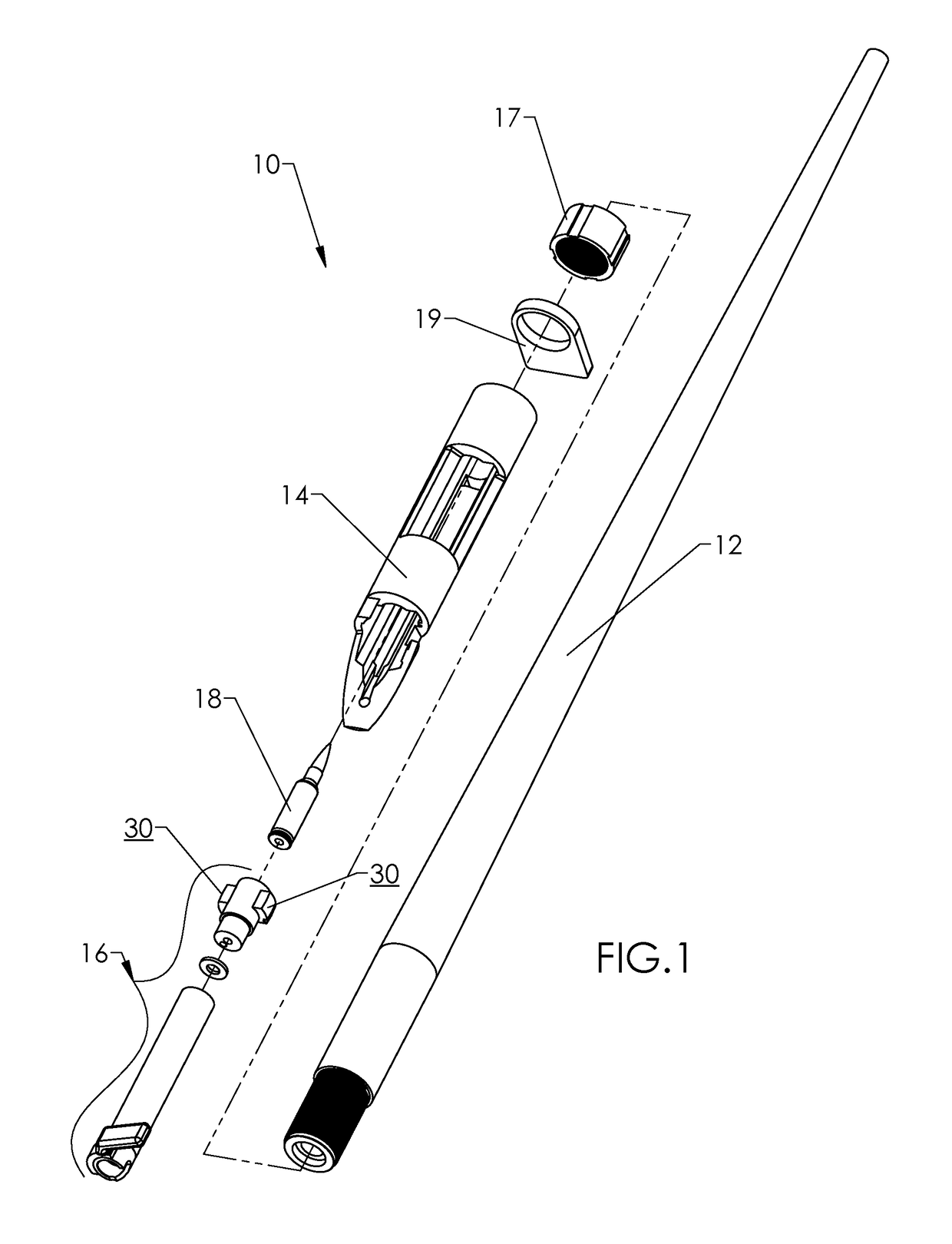
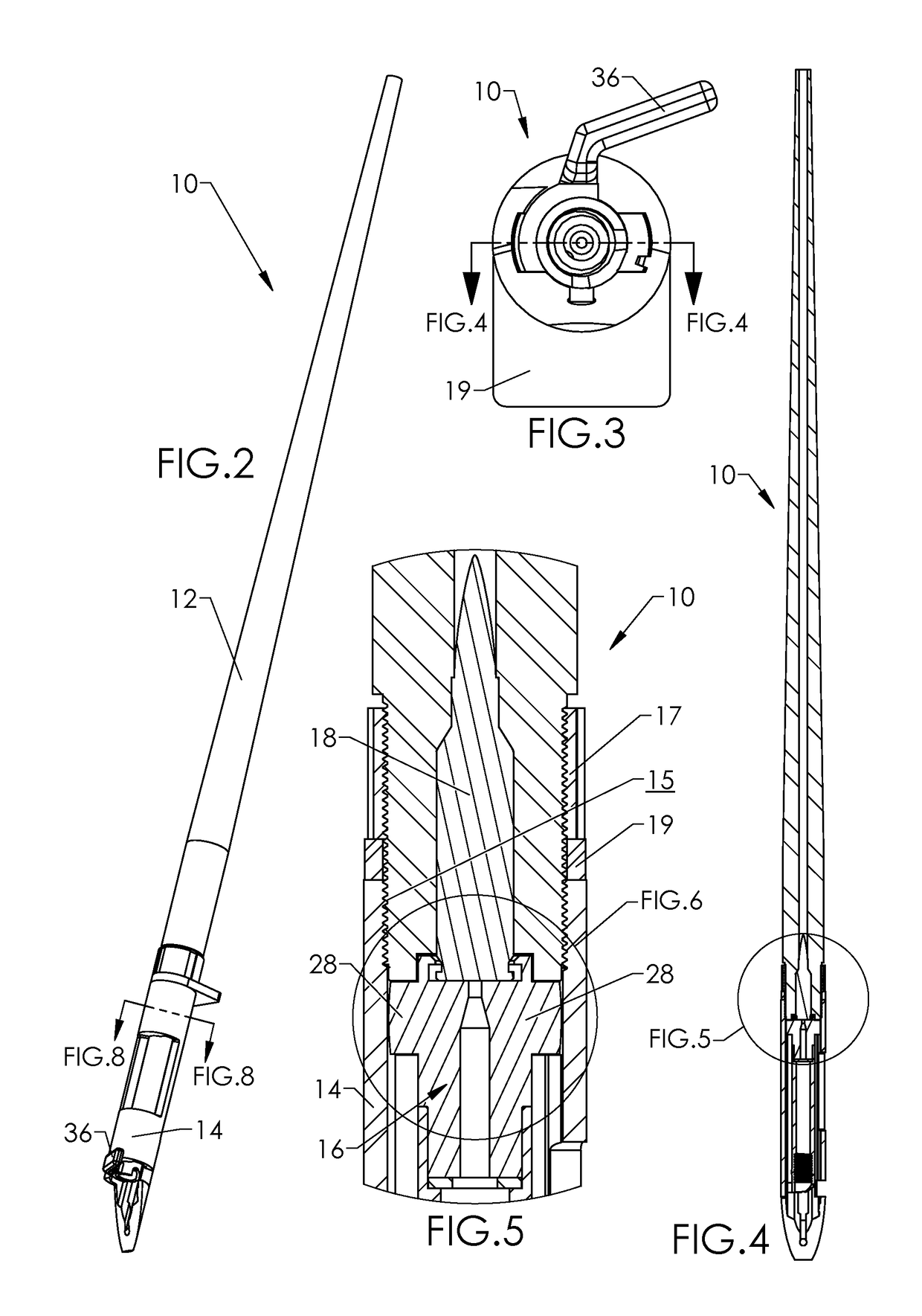
[0043]Components and operation of a bolt action rifle are shown in the drawings and detailed in this document as an example of one type of firearm / action that may comprise one or more of the adaptations disclosed herein.

[0044]When a bolt handle is lifted, usually 60-90 degrees (depending on design) from the “locked” or “battery” position, the bolt moves to extract and eject any spent cartridge and moves into the unlocked / cocked position in which a firing pin is spring loaded in a position ready to strike a primer on the next cartridge case to be fired. The bolt in this unlocked position is enabled to move rearwardly in the boltway to collect and engage a new cartridge, so that, when the bolt is then pushed forward, it forces the new cartridge into the firing chamber. Then the bolt can be rotated, by rotating the bolt handle downwards, into the locked position. In this position, the rifle is ready to have the trigger pull...


PUM


Abstract

Components of a firearm having a bolt with locking lugs improve shooting accuracy, due to increased coaxial alignment between the bolt, the cartridge, the receiver, and / or the barrel of a firearm. The receiver inner surface is shaped for lug-cleaning and for close tolerance / mating with the lugs only in the locked position and also with a non-threaded, axial surface of the barrel. Thus, the mating surfaces that are instrumental and / or that mainly control coaxial alignment of the receiver, bolt, and barrel are located between the lug stops and the threaded end of the receiver. The lugs may be axially curved or otherwise axially non-linear to tolerate dirt and other debris in a field environment.

Description

BACKGROUND OF THE DISCLOSED TECHNOLOGY[0001]Field of the Disclosed Technology[0002]This invention relates generally to firearms comprising a bolt having locking lugs. More particularly, this invention relates to improvements in coaxial alignment of components of such a firearm, and preferably also limiting the effect of rain, water, freezing water, snow, ice, dirt, vegetation, and / or other elements entering the firearm in a field environment, for example, during target shooting, hunting, or combat in inclement, uncontrolled, or unclean environments.[0003]Background / Related Art[0004]Firearms having an action comprising a bolt with locking lugs are well-known and may feature different types of bolt actuation, for example, bolt-handle action, lever action, pump action, automatic action, and semi-automatic action. Conventionally, there has been a compromise in the design of such firearms between accuracy and tolerance to elements that may enter and interfere with the firearm action. A k...

Claims


Application Information

Patent Timeline
Patent Type & Authority Patents(United States)
IPC IPC(8): F41A3/22F41A3/66F41A21/48
CPCF41A3/22F41A21/482F41A3/66
Inventor SCHENKER, DAVID PAULJOHNSTON, PATRICK EDWIN
Owner FOSTER RONALD ANDREW
Why Eureka
Try Eureka