Eureka AIR delivers breakthrough ideas for toughest innovation challenges, trusted by R&D personnel around the world.

Capacitive touch panel with height determination function

a capacitive touch panel and function technology, applied in the field of capacitive touch panel devices, can solve the problems of inability to determine the height of objects, unreliable operation, and inability to detect multiple simultaneous touch input events, and achieve the effect of accurately and reliably detecting the height of objects

Active Publication Date: 2018-11-13
SHARP KK
View PDF13 Cites 6 Cited by
  • Summary
  • Abstract
  • Description
  • Claims
  • Application Information

AI Technical Summary

Benefits of technology

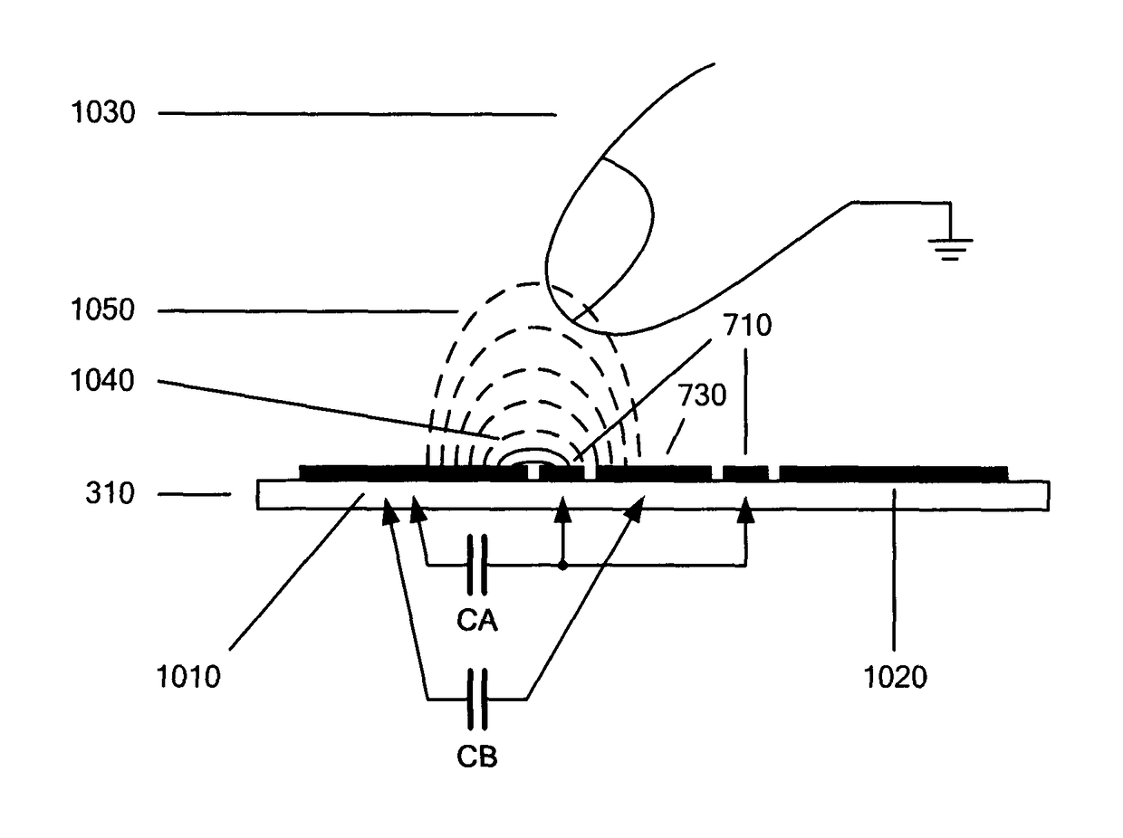
[0012]The capacitive touch panel of the present invention provides a means of accurately and reliably detecting the height of an object above the surface of a touch panel. The touch panel includes an electrode array comprising a plurality of drive and sense electrodes. The sense electrodes or the drive electrodes may be arranged as pairs such that two sense electrodes (or drive electrodes) are provided at every intersection in the array. The electrodes are further arranged such that, for example, a first sense electrode of a sense electrode pair is separated from a drive electrode by a shorter distance, in the plane of the sensor substrate, than a second sense electrode of the sense electrode pair.
[0013]Since the first sense electrode is closer to the drive electrodes at any given intersection of drive electrode and sense electrode pair, most of the capacitive coupling between this electrode and the drive electrode happens close to the substrate. The response of the first sense electrode is therefore most heavily weighted towards objects in very close proximity to the sensor. For the second sense electrode, which is more distant from the drive electrode, the coupling is less concentrated at the surface of the sensor substrate. The response of the second sense electrode is therefore less heavily weighted towards objects in contact with the sensor substrate. By comparing measurement results from first and second sense electrodes it is possible to determine the height of an object independently of its size, conductivity and resistance to ground.
[0014]This approach is advantageous over the prior art because it is applicable to projected capacitance sensor matrices, such as those used in the touch screens of mobile telephones. It is advantageous over ‘triangulation’, where the response magnitude from different intersections is compared, because the new method is simpler and requires measurements from one intersection only.

Problems solved by technology

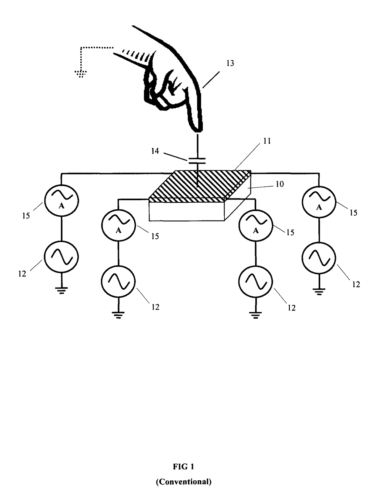
Although simple in construction and operation, surface capacitive type touch panels are unable to detect multiple simultaneous touch input events as occurs when, for example, two or more fingers are in contact with the touch panel.
However, FIG. 3 illustrates two cases that may typically cause unreliable operation.
It is therefore not possible to determine object height by examining the magnitude of the capacitance change alone.
However, using this method it can still be difficult to separate the object's size from its height.
Similarly, the calculation becomes complex when the position of multiple objects must be determined, at some distance above the sensor substrate.
This means that the height determination algorithm becomes ill-conditioned when determining whether actual contact has been made with the touch sensor substrate.
However, this method may not be applied to projected capacitance sensor matrices such as those used in touch panels.
Accordingly, there exists no satisfactory means of reliably determining an object's height using a projected capacitance sensor.
As described above known schemes are either ill-conditioned, computationally intensive, or do not apply to projected capacitance sensor matrices.

Method used


Image

  • Capacitive touch panel with height determination function
  • Capacitive touch panel with height determination function
  • Capacitive touch panel with height determination function

Examples


second embodiment

[0137]In accordance with the invention, shown in FIG. 12, the electrode array includes a plurality of drive electrodes and sense electrodes in which the drive electrodes are arranged in pairs such that two drive electrodes are provided at every intersection in the array (e.g., at each row-column intersection there is formed a second electrode group that includes at least two drive electrodes and at least one sense electrode). Each drive electrode pair includes a first drive electrode, drive electrode A 1170, and a second drive electrode, drive electrode B. Drive electrode B 1160 may have a diamond geometry, while drive electrode A 1170 may be split into two halves that run either side of drive electrode B 1160. The electrode arrangement may be symmetrical around the centre line of drive electrode B. In this way, drive electrode B 1160 is more distant from each sense electrode than drive electrode A 1170. In this way, the mutual coupling capacitor between drive electrode A and the se...

sixth embodiment

[0144]In accordance with the invention, an electrode array includes a sense electrode pair formed by a first and second dual-function electrode as described in co-pending U.S. application Ser. No. 13 / 435,898 filed on Mar. 30, 2012, which is herein incorporated in full by reference. As shown in FIG. 17, the majority of the area of the first dual-function electrode, sense electrode A 1410, approaches the odd numbered drive electrodes 1420 closely, while the majority of the area of second dual-function electrode, sense electrode B 1430, approaches the even numbered drive electrodes 1440 closely. Therefore, when one of the odd numbered drive electrodes 1420 is excited, it forms a coupling capacitance to sense electrode A 1410 over a short distance, and a coupling capacitance to sense electrode B 1430 over a longer distance, and the ratio of the change in the drive to sense capacitances, CA / CB, may be examined in order to determine object height. However, when one of the even numbered dr...

seventh embodiment

[0145]In accordance with the invention, the drive and sense electrodes are interdigitated. In a conventional touch sensor, these interdigitated electrodes may appear as shown in FIG. 18, where drive electrodes 1510 tessellate with sense electrodes 1520. The present invention may be applied to this conventional geometry in the manner shown in FIG. 19, where sense electrode A 1610 runs between sense electrode B 1620 and the interdigitated drive electrode 1510. This embodiment may be advantageous over the previous embodiments because the interdigitated geometry provides a larger fringing capacitance between the drive and sense electrodes, and therefore a greater signal swing.

[0146]An eighth embodiment uses any one of the electrode geometries described in the previous embodiments. Like the previous embodiments, the ratio of the two measured capacitances is used to determine the height of an object in proximity to the sensor, and this ratio is compared to a look-up table in order to dete...


PUM


Abstract

A capacitive touch sensor includes a sensor substrate and an array of electrode elements formed over the sensor substrate. Each electrode element of the array includes at least one of a first electrode group comprising at least two drive electrodes and at least one sense electrode, or a second electrode group comprising at least two sense electrodes and at least one drive electrode. The respective electrodes of the first or second electrode group are arranged to form multiple capacitances over different coupling distances. A controller is operatively coupled to the array of electrode elements, the controller configured to determine a distance of an object relative to the surface of the touch sensor based on variations in the multiple capacitances.

Description

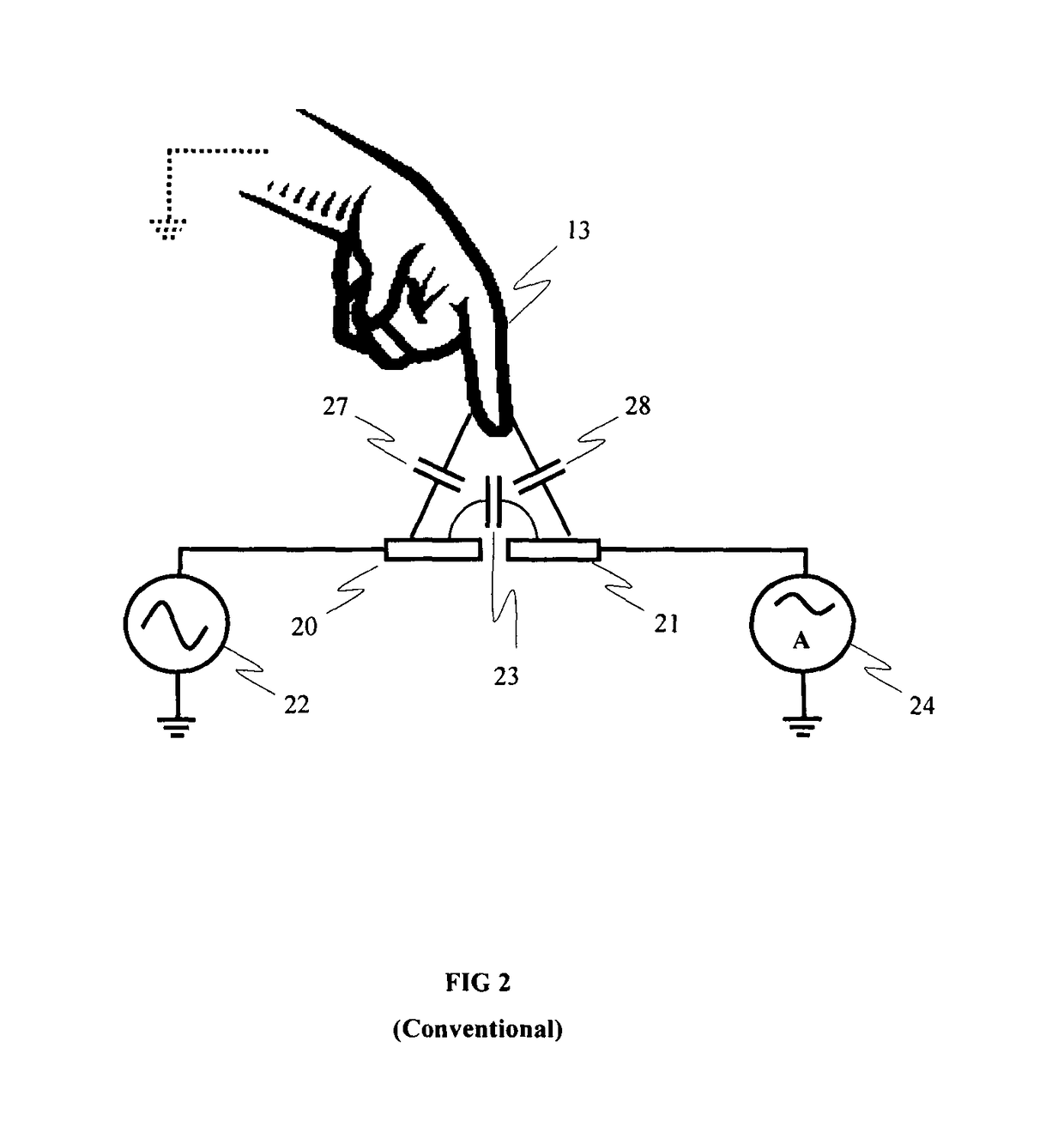
TECHNICAL FIELD AND APPLICATIONS OF THE INVENTION[0001]The present invention relates to touch panel devices. In particular, this invention relates to capacitive type touch panels. Such a capacitive type touch panel device may find application in a range of consumer electronic products including, for example, mobile phones, tablet and desktop PCs, electronic book readers and digital signage products.BACKGROUND ART[0002]Touch panels have recently become widely adopted as the input device for high-end portable electronic products such as smart-phones and tablet devices. Although, a number of different technologies can be used to create these touch panels, capacitive systems have proven to be the most popular due to their accuracy, durability and ability to detect touch input events with little or no activation force.[0003]The most basic method of capacitive sensing for touch panels is the surface capacitive method (also known as self-capacitance), for example as disclosed in U.S. Pat. ...

Claims


Application Information

Patent Timeline
Patent Type & Authority Patents(United States)
IPC IPC(8): G06F3/044
CPCG06F3/044G06F2203/04101G06F3/04166G06F3/0443G06F3/0445G06F3/0446G06F3/0448
Inventor COULSON, MICHAEL PAULBROWN, CHRISTOPHER JAMESSLAMKUL, DAUREN
Owner SHARP KK
Why Eureka
Eureka Blog
Learn More