
Medium-range magnetostrictive ultrasonic guided wave scanner systems and methods

a magnetostrictive ultrasonic guided wave and scanner technology, applied in the field of non-destructive inspection, can solve the problems of inability to detect the entire region, lack of axial and lateral resolution in many applications, and inherent limitations of this technology

Active Publication Date: 2018-11-06
FUKUOKA BROADCASTING CORPORATION
View PDF32 Cites 4 Cited by
  • Summary
  • Abstract
  • Description
  • Claims
  • Application Information

AI Technical Summary

Benefits of technology

This patent describes a system and method for non-destructive inspection of a structure using a magnetostrictive scanner probe and a ferromagnetic strip. The scanner probe applies a time-varying current to the ferromagnetic strip to induce a time-varying magnetization, which causes guided waves to be generated in the structure. The reflected guided waves are detected and processed to create a two-dimensional image of the structure. This technology allows for precise and accurate inspection of structures without causing any damage.

Problems solved by technology

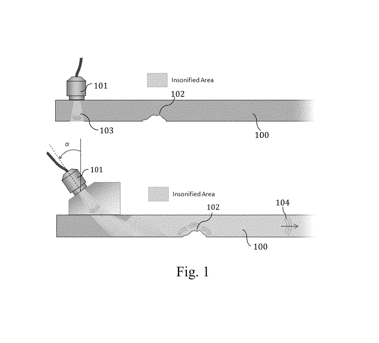
However, due to the nature of the guided waves and associated electronics used in such applications, there are inherent limitations of this technology.
Two of these limitations are the existence of an uninspectable region, i.e. ‘dead zone’, around the transducer and a lack of axial and lateral resolution in many applications.

Method used


Image

  • Medium-range magnetostrictive ultrasonic guided wave scanner systems and methods
  • Medium-range magnetostrictive ultrasonic guided wave scanner systems and methods
  • Medium-range magnetostrictive ultrasonic guided wave scanner systems and methods

Examples


Embodiment Construction

[0020]This description of the exemplary embodiments is non-limiting and is intended to be read in conjunction with the accompanying drawings, which are to be considered part of the entire written description.

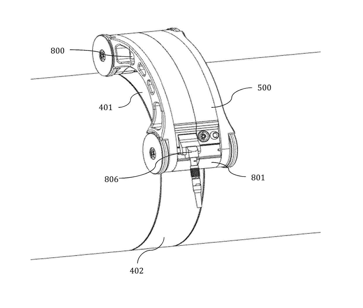
[0021]The disclosed medium-range magnetostrictive ultrasonic guided wave scanner system generates two-dimensional scan images for the purposes of non-destructive inspection of pipes, plates, and shells by sending and receiving shear horizontal-type guided waves in said structures. The system includes at least one pulser / receiver / processor, at least one sensor coil, at least one ferromagnetic strip, at least one biasing magnet, a position encoder, and a probe body upon which at least the coil and encoder are mounted. The pulser / receiver / processor electronics sub-system and software to perform data analysis and hardware control also can be mounted in or on the probe body.

[0022]In some embodiments, the sensor coil is a flat flexible cable (FFC), although the sensor coil also can be...


PUM

PropertyMeasurementUnit
frequenciesaaaaaaaaaa
distancesaaaaaaaaaa

Abstract

An inspection system includes a magnetostrictive scanner probe, a ferromagnetic strip, at least one magnet, and a processor. The magnetostrictive scanner probe includes a probe body for supporting at least one flexible sensor coil and a position encoder. The ferromagnetic strip is configured to be coupled to a structure, and the at least one magnet is configured to apply a biasing magnetization to the ferromagnetic strip. The processor is configured to cause a time-varying current to be generated in the at least one flexible sensor coil to induce a time-varying magnetization in said ferromagnetic strip perpendicular to said biasing magnetization to generate shear horizontal-type guided wave energy into said structure, and process reflected shear horizontal-type guided wave energy received by the at least one flexible sensor coil as the probe is moved relative to said structure to generate at least one two-dimensional image of a region of said structure.

Description

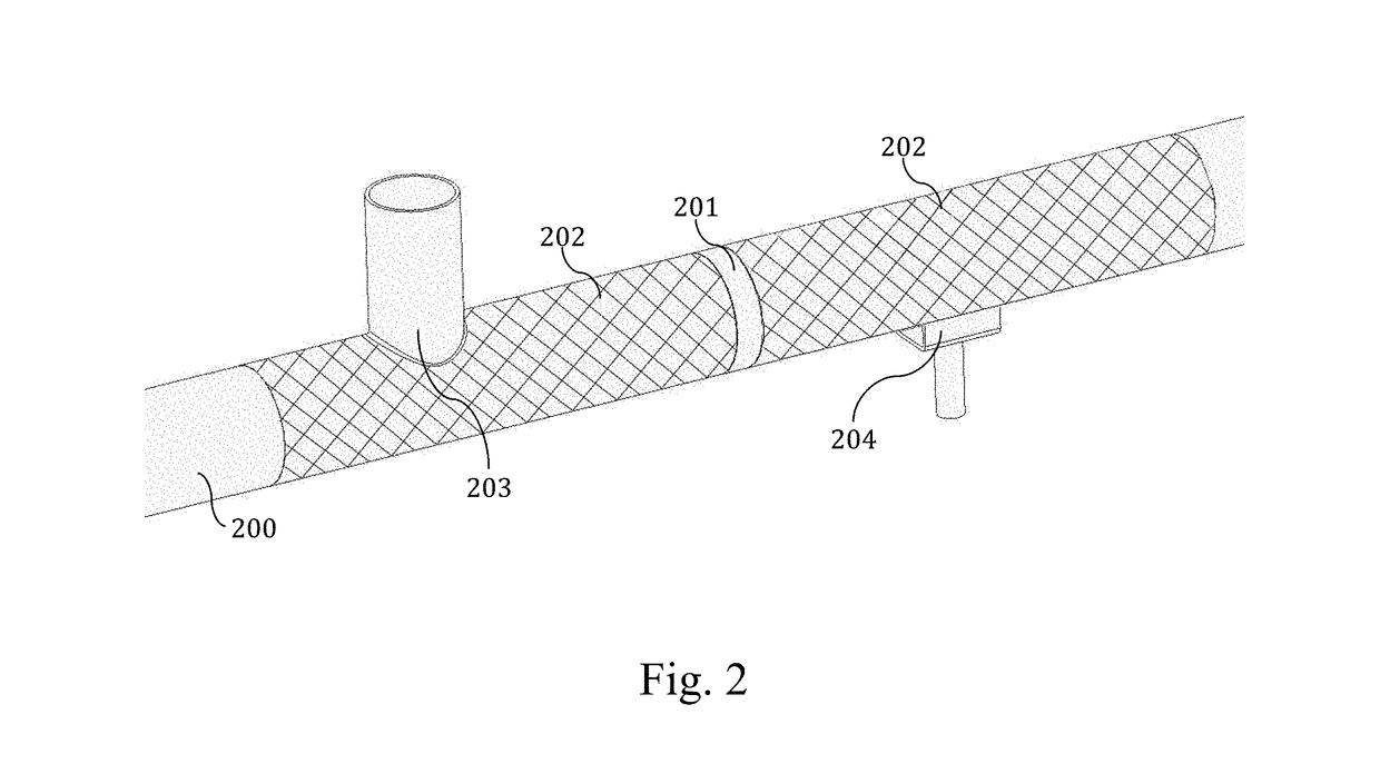
CROSS-REFERENCE TO RELATED APPLICATION(S)[0001]This application claims priority to U.S. Provisional Patent Application No. 62 / 116,186, filed Feb. 13, 2015, the entirety of which is incorporated by reference herein.FIELD[0002]The disclosed systems and methods relates to the non-destructive inspection of sections of pipes, plates, and shells using ultrasonic guided waves.BACKGROUND INFORMATION[0003]Ultrasonic guided wave techniques are utilized in a wide range of non-destructive inspection applications including those for pipes, plates, and shells comprised of metals, composites, and other materials. Guided waves are elastic waves propagating in a bounded structure that is utilized as a waveguide to efficiently transmit one or more wave modes along the structure. One of the foremost benefits of guided waves over other non-destructive inspection techniques is the ability of said waves to propagate over long distances, in many cases hundreds of feet, and to inspect inaccessible or hidde...

Claims


Application Information

Patent Timeline
Patent Type & Authority Patents(United States)
IPC IPC(8): G01N29/24G01N29/265
CPCG01N29/2412G01N29/2493G01N29/265G01N2291/2634G01N2291/0422G01N2291/0425
Inventor OWENS, STEVEN E.BORIGO, CODY J.ROSE, JOSEPH L.LOPEZ, BORJA
Owner FUKUOKA BROADCASTING CORPORATION
Learn More