
Vertical-transition structure

a technology of vertical transition and structure, applied in the direction of waveguide type devices, coupling device connections, high frequency circuit adaptations, etc., can solve the problems of severe insertion loss of the vertical transition at high frequencies, and introduce the “insertion loss” of the vertical transition between the two transmission lines. , to achieve the effect of improving the transmission passband of the vertical transition, reducing the insertion loss, and improving the insertion loss of the vertical transition

Active Publication Date: 2018-10-30
NAT TAIPEI UNIV OF TECH
View PDF1 Cites 5 Cited by
  • Summary
  • Abstract
  • Description
  • Claims
  • Application Information

AI Technical Summary

Benefits of technology

The present invention provides a vertical transition structure that improves the transmission passband and reduces the insertion loss between a coaxial cable and a microstrip line. This structure features an eccentric design and a metallic ring to minimize the resonant dip and improve the smooth transformation of the electromagnetic field distribution. Overall, this structure is suitable for high-frequency applications in microwave engineering.

Problems solved by technology

However, due to different electromagnetic field distributions of the two different transmission lines, “insertion loss” is introduced at their joint.
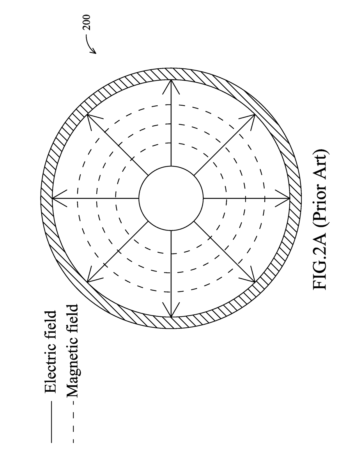
The two electromagnetic field distributions shown in FIGS. 2A and 2B are obviously different, which results in severe “insertion loss” of the vertical transition between the two transmission lines at high frequencies.
In addition, the resonant response of the coaxial connector at higher-order modes also leads to the insertion loss of the vertical transition at high frequencies.
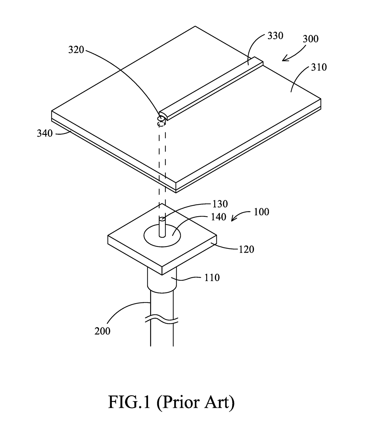
The structure shown in FIG. 1, however, only simply connects the coaxial cable 200 vertically to the microstrip line 300, which does not solve the problem caused by the abrupt change of the electromagnetic field distributions at the joint of the two transmission lines, nor the problem caused by the resonant response of the coaxial connector.
Consequently, the conventional vertical transition cannot effectively reduce the severe insertion loss at high frequencies, which restrains its 1-dB passband.
Therefore, the conventional design is not suitable for applications at high frequencies.

Method used


Image

  • Vertical-transition structure
  • Vertical-transition structure
  • Vertical-transition structure

Examples


Embodiment Construction

[0024]In the following the detailed description of a preferred embodiment accompanied by its corresponding drawings clearly manifests the early statements on this invention and other technical contents, features, and functions. In this regard, the direction-related terms, such as “top,”“bottom,”“left,”“right,”“front,”“back,” etc., are used with reference to the orientations of the objects in the Figure(s) being considered. The components of the present invention can be positioned in a number of different orientations. As such, the direction-related terms are used for the purposes of illustration and by no means as restrictions to the present invention. On the other hand, the sizes of objects in the schematic drawings may be overstated for the purpose of clarity. It is to be understood that other likely employed embodiments or possible changes made in the structure of the present invention should not depart from the scope of the present invention. Also, it is to be understood that th...


PUM


Abstract

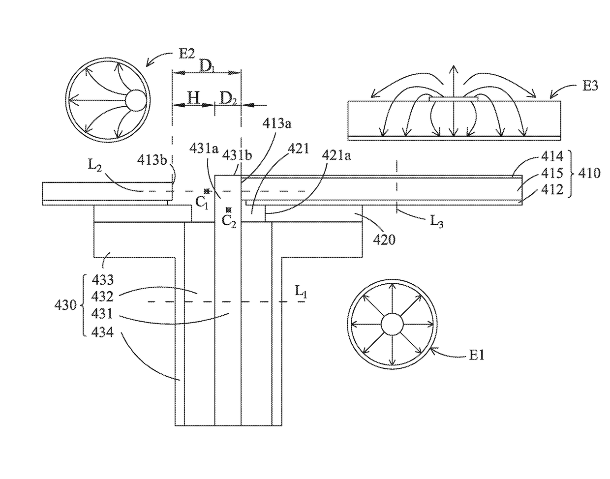
A vertical-transition structure comprises a microstrip line and a combination of a coaxial connector and a metallic ring underneath the microstrip line. A first through hole is created next to the microstrip line and near one end of its signal line. The metallic ring has a second through hole. The coaxial connector has a center conductor including an extended portion to be inserted into the second through hole via its center, and subsequently through the first through hole to connect to the signal line vertically. Specially, the extended portion is not inserted through the center of the first through hole. The present structure can improve the high-frequency insertion loss of the vertical transition caused by the sudden change of electromagnetic field distributions from a coaxial line to a microstrip line and the resonant response of the coaxial connector, and therefore, increase the 1-dB transmission passband of the vertical transition substantially.

Description

BACKGROUND OF THE INVENTION(1) Field of the Invention[0001]The present invention relates to a vertical-transition structure, particularly for one that is suitable for vertical signal transmission at high frequencies.(2) Description of the Prior Art[0002]In microwave communications, vertical transitions between different transmission lines, such as coaxial cables, microstrip lines, coplanar waveguides, waveguides and so on, are often encountered during device testing or system integration. Among them, the vertical transition between a coaxial cable and a microstrip line is the most popular one. In order to transmit signals vertically between these two transmission lines, the conventional approach is to use a flange-mount coaxial connector to provide vertical connection between the coaxial cable and the microstrip line.[0003]Please refer to FIG. 1, the conventional vertical transition comprises a flange-mount coaxial connector 100, a coaxial cable 200 and a microstrip line 300. The fl...

Claims


Application Information

Patent Timeline
Patent Type & Authority Patents(United States)
IPC IPC(8): H01P5/08H01R24/44H01R24/52H01R12/75H01R103/00
CPCH01P5/085H01R24/44H01R24/52H01R2103/00H01R12/75H05K1/0237H05K1/116H05K3/32H05K2201/09809H05K2201/10356
Inventor LI, ERIC S.HUANG, HONG-WEI
Owner NAT TAIPEI UNIV OF TECH
Learn More