
Mechanically sealed tube for laser sustained plasma lamp and production method for same

a plasma lamp and mechanical sealing technology, applied in the manufacture of electric discharge tubes/lamps, cold cathode manufacture, electrode systems, etc., can solve the problems of affecting the operation of the lamp

Active Publication Date: 2018-10-23
EXCELITAS TECH
View PDF154 Cites 11 Cited by
  • Summary
  • Abstract
  • Description
  • Claims
  • Application Information

AI Technical Summary

Benefits of technology

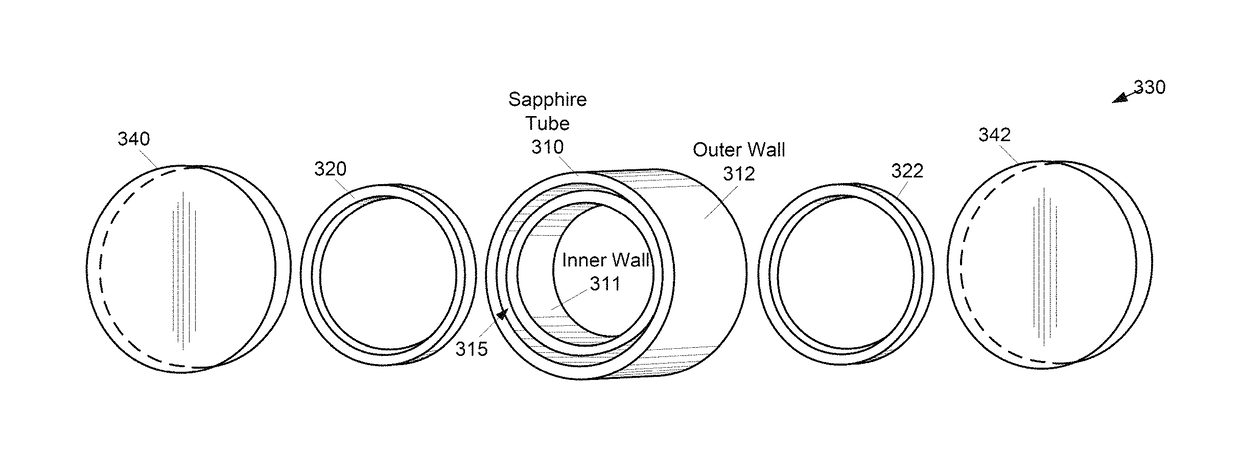
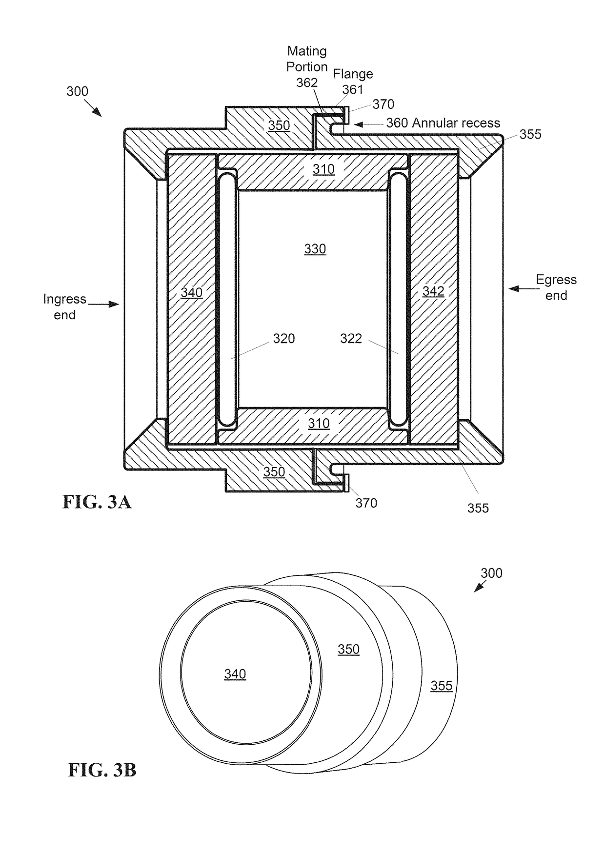
The present invention provides a mechanically sealed tube for a laser sustained plasma lamp and a production method for the same. The chamber assembly is made up of a chamber tube, ingress and egress sapphire windows, and two metal seal rings. A mechanical clamping structure is used to bring the sapphire windows together without welding or brazing them to the chamber tube. This results in a more reliable and durable laser sustained plasma lamp.

Problems solved by technology

The anode and / or cathode may wear and emit particles.
Such particles can impair the operation of the lamp, and cause degradation of the anode and / or cathode.
Because of said cooling, the operating temperature of the lamp is not ideal to minimize gas turbulence in the envelopes of such lamps.
Similarly, some existing laser sustained plasma lamps are formed of a material that is not compatible with a mercury enhanced fill gas to obtain high internal operating pressure.

Method used


Image

  • Mechanically sealed tube for laser sustained plasma lamp and production method for same
  • Mechanically sealed tube for laser sustained plasma lamp and production method for same
  • Mechanically sealed tube for laser sustained plasma lamp and production method for same

Examples


Embodiment Construction

[0021]The following definitions are useful for interpreting terms applied to features of the embodiments disclosed herein, and are meant only to define elements within the disclosure.

[0022]As used within this disclosure, a lens refers to an optical element that redirects / reshapes light passing through the optical element. In contrast, a mirror or reflector redirects / reshapes light reflected from the mirror or reflector.

[0023]As used within this disclosure, a direct path refers to a path of a light beam or portion of a light beam that is not reflected, for example, by a mirror. A light beam passing through a lens or a flat window is considered to be direct.

[0024]As used within this disclosure, “substantially” means “very nearly,” or within normal manufacturing tolerances. For example, a substantially flat window, while intended to be flat by design, may vary from being entirely flat based on variances due to manufacturing.

[0025]Reference will now be made in detail to embodiments of t...


PUM


Abstract

A laser sustained plasma lamp includes a mechanically sealed pressurized chamber assembly (330) configured to contain an ionizable material. The chamber assembly is bounded by a chamber tube (310), an ingress sapphire window (340), a first metal seal ring (320) configured to seal against the chamber tube ingress end and the ingress sapphire window, an egress sapphire window (342), and a second metal seal ring (322) configured to seal against the chamber tube egress end and the egress sapphire window. A mechanical clamping structure (350, 355) external to the chamber assembly is configured to clamp across at least a portion of the ingress sapphire window and the egress sapphire window. The ingress sapphire window and the egress sapphire window are not connected to the chamber tube via welding and / or brazing.

Description

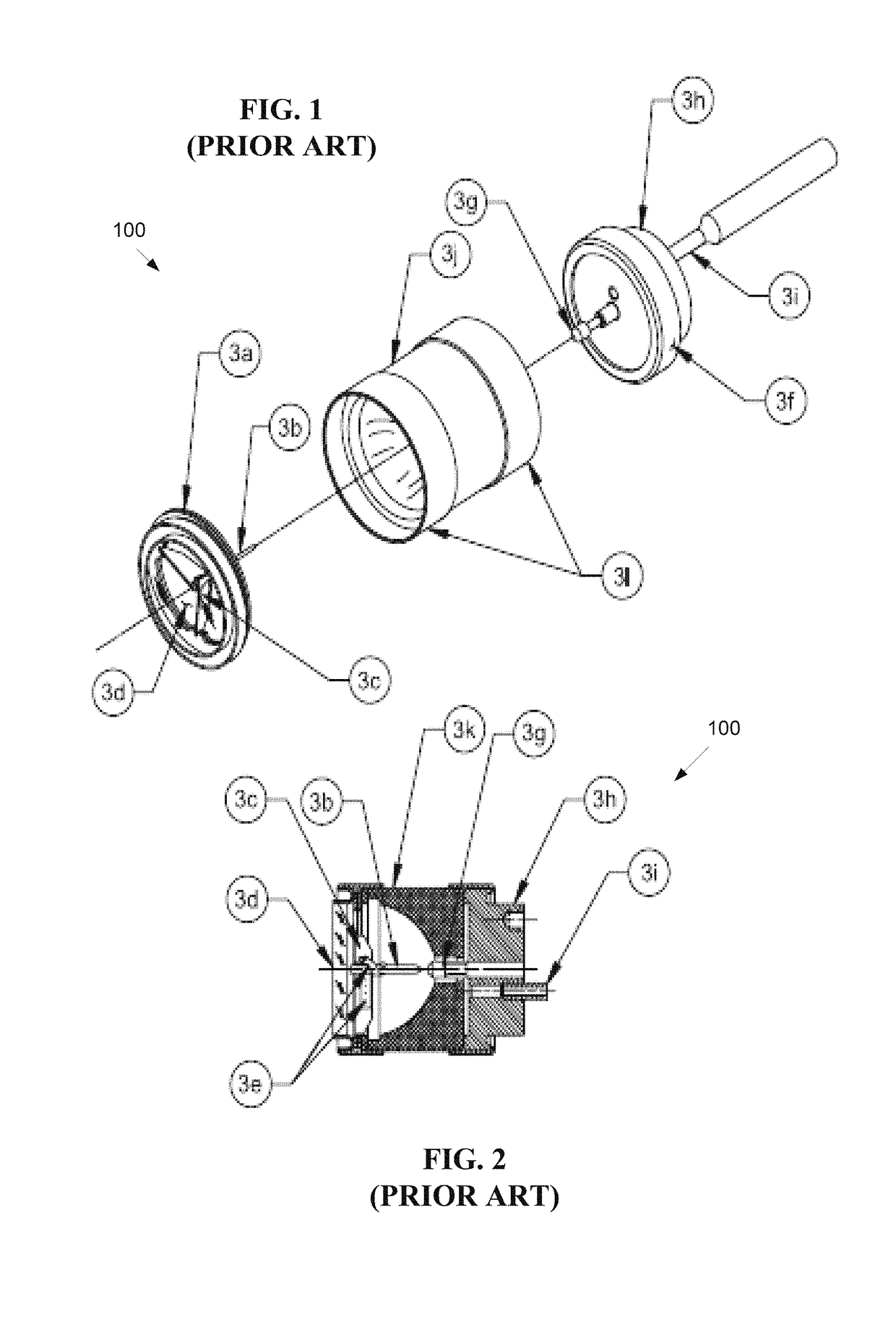
FIELD OF THE INVENTION[0001]The present invention relates to illumination devices, and more particularly, is related to high-intensity arc lamps.BACKGROUND OF THE INVENTION[0002]High intensity arc lamps are devices that emit a high intensity beam. The lamps generally include a gas containing chamber, for example, a glass bulb, with an anode and cathode that are used to excite the gas (ionizable medium) within the chamber. An electrical discharge is generated between the anode and cathode to provide power to the excited (e.g. ionized) gas to sustain the light emitted by the ionized gas during operation of the light source.[0003]FIG. 1 shows a pictorial view and a cross section of a low-wattage parabolic prior art Xenon lamp 100. The lamp is generally constructed of metal and ceramic. The fill gas, Xenon (Xe), is inert and nontoxic. The lamp subassemblies may be constructed with high-temperature brazes in fixtures that constrain the assemblies to tight dimensional tolerances. FIG. 2 s...

Claims


Application Information

Patent Timeline
Patent Type & Authority Patents(United States)
IPC IPC(8): H01J61/36H01J61/02H05H1/46H01J61/06H01J61/54H01J61/16
CPCH01J61/361H01J61/54H01J61/025H01J61/06H05H1/46H01J61/16H01J65/042H01J9/266
Inventor BLONDIA, RUDIDOUGHTY, DOUGLAS A.KISS, JOHNROBERTS, ROY D.
Owner EXCELITAS TECH
Learn More