Flow-rate measurement nozzle with velocity pressure pickup channel

Active Publication Date: 2018-10-23
GRENNING FREDERICK H
View PDF20 Cites 0 Cited by
  • Summary
  • Abstract
  • Description
  • Claims
  • Application Information

AI Technical Summary

Benefits of technology

This patent describes an apparatus and method for measuring the velocity pressure of fluid flowing through a fluid line. This is achieved through a nozzle with a side wall that has a larger cross-sectional area at the inlet end than the outlet end, which allows for the measurement of the velocity pressure of the fluid. The nozzle is connected to an upstream line through which the fluid flows. The apparatus also includes a differential pipe that is in fluid communication with the nozzle and allows for the measurement of the velocity pressure of the fluid. This invention enables accurate measurement of the velocity pressure of fluid flow in a simple and reliable way.

Problems solved by technology

Due to inexact orifice diameter, excessive turbulence (which may cause fluctuations in the observed pressure level of + / −10 psi), and incorrect pitot tube positioning, these options give the least dependable readings.
A general problem with pitot tubes is that they are difficult to position to obtain accurate pressure readings.
As the pitot tube placement deviates from these requirements, the less accurate the pressure readings will be.
Additionally, the pitot tube structure extends partially into the fluid line, and therefore is susceptible to damage by solids entrained in the fluid.
Conventional pitot tubes and other flow testing apparatus are also susceptible to inaccuracies due to turbulent fluid flow.
While the pitotless nozzle of the '375 patent represented an improvement over prior devices, the range of flow-rates that it could measure was limited and improved accuracy of pressure measurements used to calculate flow-rates was still desired.

Method used


Image

  • Flow-rate measurement nozzle with velocity pressure pickup channel
  • Flow-rate measurement nozzle with velocity pressure pickup channel
  • Flow-rate measurement nozzle with velocity pressure pickup channel

Examples


Embodiment Construction

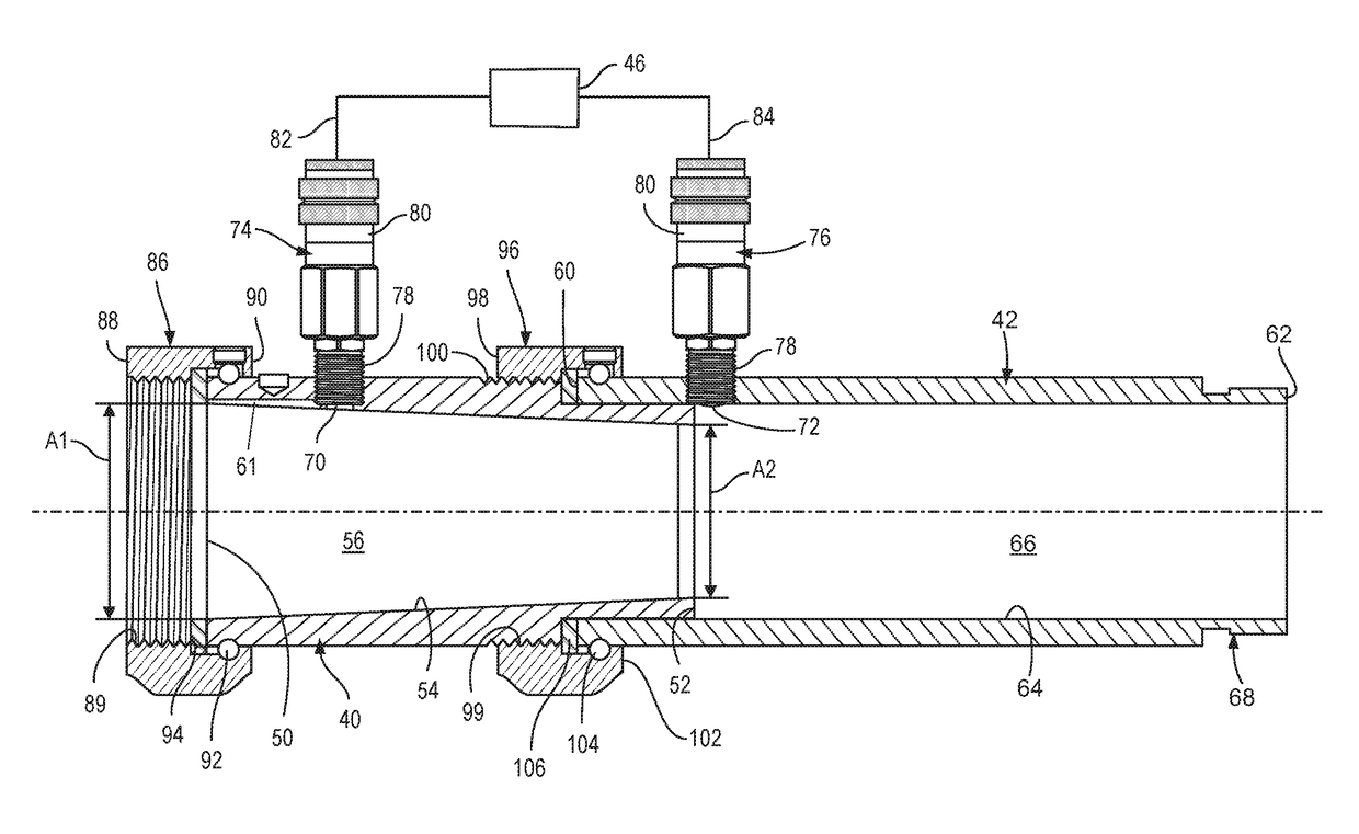
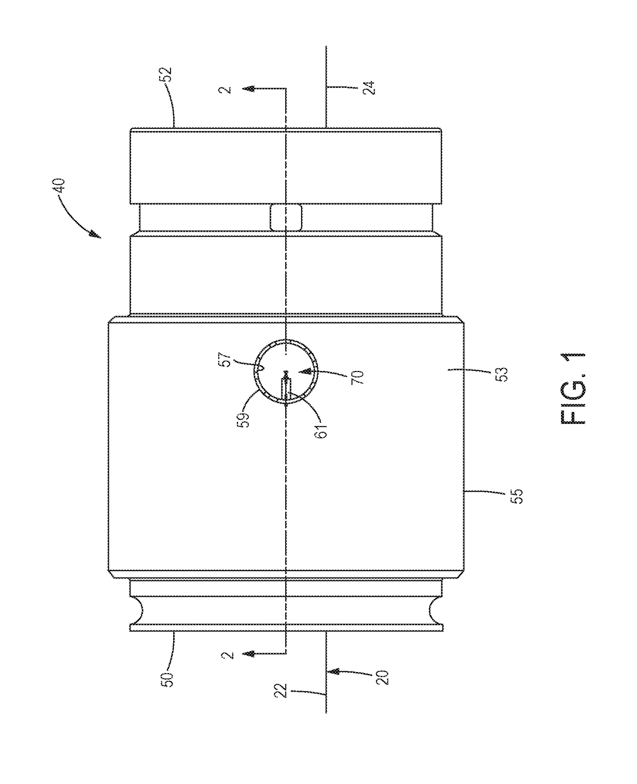
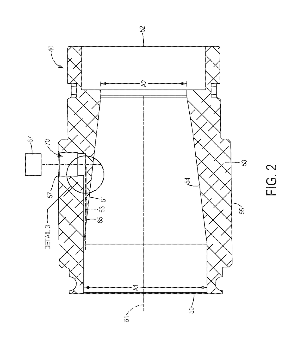
[0020]Embodiments of testing equipment and methods used to measure a fluid flow through a fluid line are disclosed herein. The testing equipment includes a nozzle configured to generate a constant fluid pressure and having a first pressure port. A first pressure port extends through a side wall of the nozzle and includes a velocity pressure pickup channel facing the direction of fluid flow through the nozzle, so that a gauge coupled to the first pressure port can measure a velocity pressure of the fluid. By providing a channel through which velocity pressure of the fluid can be detected, the nozzle is capable of measuring an expanded range of fluid flow rates, and the flow rate measurements are more accurate across the entire range of fluid flow rates. In some embodiments, a differential chamber is coupled to the nozzle and includes a second pressure port positioned to communicate with the fluid immediately downstream of the nozzle, and a differential gauge may be operably coupled t...


PUM


Abstract

Velocity pressure measuring apparatus and methods include a nozzle having a nozzle inlet end and a nozzle outlet end. A side wall of the nozzle extends along a nozzle axis and has an exterior surface and an interior surface. The interior surface defines a nozzle chamber and has a nozzle inlet cross-sectional area at the nozzle inlet end that is greater than a nozzle outlet cross-sectional area at the nozzle outlet end. A first pressure port extends through the side wall from the exterior surface of the nozzle to the interior surface of the nozzle, and includes a velocity pressure pickup channel extending along a channel axis oriented substantially parallel to the nozzle axis.

Description

FIELD OF THE DISCLOSURE[0001]The present disclosure relates generally to fluid flow rate measurement, and more particularly to methods and apparatus for measuring differential pressure of a fluid in a fluid line to determine a flow rate of the fluid.BACKGROUND OF THE DISCLOSURE[0002]Fluid flow measuring devices and methods are known for use with fluid flow systems to measure pressure of a fluid flow, which may be converted into a fluid flow rate. A pitot tubes, for example, is a device commonly used to measure pressure of a fluid flowing through a fluid line. The pitot tube may be positioned to measure fluid pressure at a specific point within the fluid line, and typically includes an opening that may be placed in the stream of the fluid flow. To obtain an accurate reading, the pitot tube must be positioned so that the opening is located in the exact center of the stream and oriented parallel to the fluid flow path. A gauge may be operably coupled to the pitot tube to provide a pres...

Claims


Application Information

Patent Timeline
IPC IPC(8): G01F1/42
CPCG01F1/42G01F1/40G01F1/44
Inventor GRENNING, FREDERICK H.
Owner GRENNING FREDERICK H
Why Eureka
Try Eureka