Eureka AIR delivers breakthrough ideas for toughest innovation challenges, trusted by R&D personnel around the world.

A Design Method for Increased Lift Wing Tip

A design method and wingtip technology, applied in aircraft parts, ground equipment, transportation and packaging, etc., can solve the problems of increasing the complexity of the manufacturing process and increasing the weight, so as to increase the complexity of the manufacturing process, reduce the weight of the structure, increase the The effect of lift

Active Publication Date: 2017-04-19
SHENYANG AIRCRAFT DESIGN INST AVIATION IND CORP OF CHINA
View PDF5 Cites 0 Cited by
  • Summary
  • Abstract
  • Description
  • Claims
  • Application Information

AI Technical Summary

Problems solved by technology

The effect of this type of winglet is more obvious, but at the same time it also increases the weight and increases the complexity of the manufacturing process

Method used


Image

  • A Design Method for Increased Lift Wing Tip
  • A Design Method for Increased Lift Wing Tip
  • A Design Method for Increased Lift Wing Tip

Examples


Embodiment Construction

[0020] The present invention will be described in further detail below through specific embodiments and in conjunction with the accompanying drawings.

[0021] The steps of the present invention include:

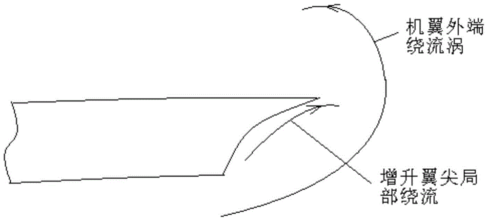
[0022] Step 1. Different from the previous design of increased wingtip, which mainly uses winglets to block the vortex flow around the wingtip, first establish a new theory that uses the reverse vortex around the wingtip to reduce the vortex flow around the wingtip. The new vorticity calculation formula is:

[0023] Γ 总 =Γ 翼尖 -Γ 增升

[0024] After the design of the special shape of the increased wing tip, the circulation of the wing tip vortex can be partially offset, thereby reducing the loss of the three-dimensional flow around the wing tip, and achieving the purpose of reducing the overall aircraft resistance and increasing the overall aircraft lift;

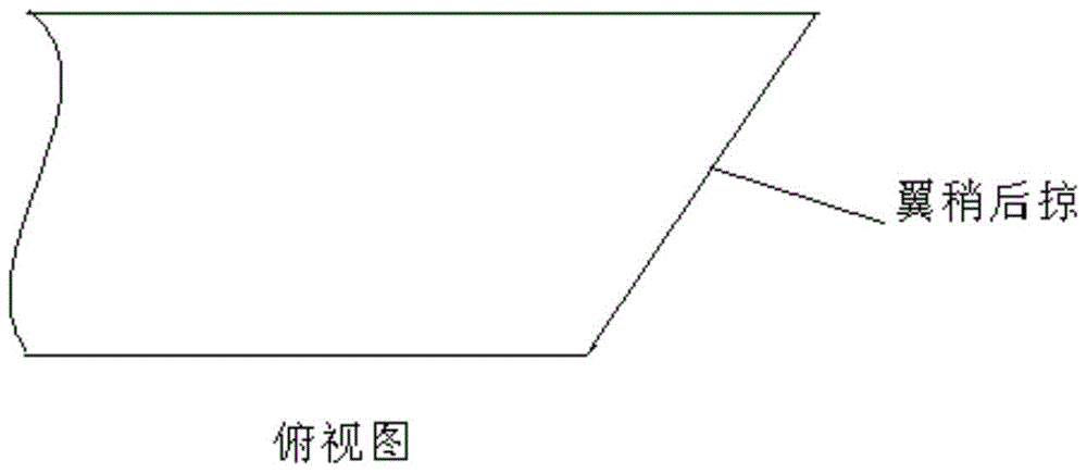
[0025] Step 2, select the appropriate wing tip average sweep angle according to the aircraft design flight M number, ...


PUM


Abstract

The invention belongs to the field of aircraft pneumatic layout design, and relates to a rising wingtip design method. The method comprises the steps of: building a vorticity calculating method for reducing the wingtip vortex streaming by using the wingtip reverse streaming vortex; designing a rising wingtip to partially counteract the circular reactor of the wingtip vortex to reduce the loss of wingtip three-dimensional streaming so as to achieve the purposes of reducing the whole aircraft resistance and improving the whole aircraft lift; calculating the position and the feature size of a space-inclined curved surface through the fluid mechanics to perform optimal adjustment and selection; and further performing the verification and the optimization for the design through a wind tunnel test. The rising wingtip design method creatively builds the resistance-reducing and lift-improving design principle of the wingtip reverse streaming vortex, and initiates the rising wingtip design principle and method capable of improving the lift while reducing the structural weight and simplifying the structural design.

Description

technical field [0001] The invention belongs to the field of aerodynamic layout design of civil aircraft, and relates to a design method for increased lift wingtips. Background technique [0002] During the development of aircraft aerodynamic layout design, engineers have been constantly striving to improve lift and reduce flight resistance. The real aircraft is limited by the size of the wingspan, and a three-dimensional flow is generated at the tip of the wing, so that the lift of the real wing is significantly smaller than that of the two-dimensional airfoil. In order to reduce the increase in drag and decrease in lift caused by wingtip vortices, aerodynamic design engineers have designed various winglets and achieved remarkable results. [0003] In modern aircraft design, most of the winglets are characterized by a small wing protruding obliquely upward from the outer end of the main wing. The main technical principle is to block and reduce the generation of wingtip vor...

Claims


Application Information

Patent Timeline
Patent Type & Authority Patents(China)
IPC IPC(8): B64F5/00
Inventor 孙聪潘英
Owner SHENYANG AIRCRAFT DESIGN INST AVIATION IND CORP OF CHINA
Why Eureka
Eureka Blog
Learn More