Ink-jet printer

a technology of inkjet printers and inkjet printers, which is applied in the direction of printing, printing, power drive mechanisms, etc., can solve the problems of reducing reducing the fpot, and requiring time for preparation processing, so as to maintain the quality of image recording and recording processing, and shorten the fpot

Active Publication Date: 2018-10-16
BROTHER KOGYO KK
View PDF5 Cites 0 Cited by
  • Summary
  • Abstract
  • Description
  • Claims
  • Application Information

AI Technical Summary

Benefits of technology

[0004]In the recent years, an attempt is made, in an information processing apparatus and a printer which are connected to each other via a communication network, to shorten FPOT (abbreviation of First Print Out Time) that is a time since a print instruction or command is input to the information processing apparatus (terminal) until a first sheet is discharged from the printer. Further, as one of the methods for shortening the FPOT, it is considered to shorten the time for a preparing processing such as the flushing processing, etc.
[0005]Conventionally, however, the amount of ink to be jetted in the flushing processing is increased or decreased depending on the state of the printer. Further, in a case that the amount of the ink to be jetted in the flushing processing becomes great, the preparation processing requires time and thus the FPOT is lowered. On the other hand, in a case that the amount of the ink jetted in the flushing processing is insufficient, the quality of image recording is lowered.
[0006]The present teaching has been made in view of the above-described situation, and an object of the present teaching is to provide an ink-jet printer capable of shortening the FPOT while maintaining the quality of image recording.
[0008]According to the above configuration, in a case that the ink amount to be jetted in the flushing processing is great, the returning position becomes distanced away from the sheet facing area. For this reason, in a case that the carriage is moved upstream in the scanning direction from the returning position up to the sheet facing area, the moving distance across which the carriage is moved becomes long. As a result, in the flushing processing executed while moving the carriage, the ink can be jetted in a required ink amount in the ensured manner, thereby making it possible to maintain the quality of image recording in the recording processing.
[0009]On the other hand, as the ink amount to be jetted in the flushing processing is smaller, the returning position becomes nearer or closer to the sheet facing area. For this reason, the time for executing the moving of the carriage in the first orientation up to the returning position corresponding to the determined ink amount, and the time for executing the moving of the carriage upstream in the scanning direction from the returning position up to the sheet facing area are shortened. Further, in this case, even if the moving distance across which the carriage is moved so as to reach the sheet facing area is short, the ink can be jetted in the required ink amount. As a result, it is possible to shorten the FPOT while maintaining the quality of image recording.
[0010]As described above, the moving distance across which the carriage is moved in the flushing processing is increased or decreased, depending on the ink amount of the ink to be jetted. Thus, is it possible to shorten the FPOT while maintaining the quality of image recording.

Problems solved by technology

Further, in a case that the amount of the ink to be jetted in the flushing processing becomes great, the preparation processing requires time and thus the FPOT is lowered.
On the other hand, in a case that the amount of the ink jetted in the flushing processing is insufficient, the quality of image recording is lowered.

Method used


Image

  • Ink-jet printer
  • Ink-jet printer
  • Ink-jet printer

Examples


Embodiment Construction

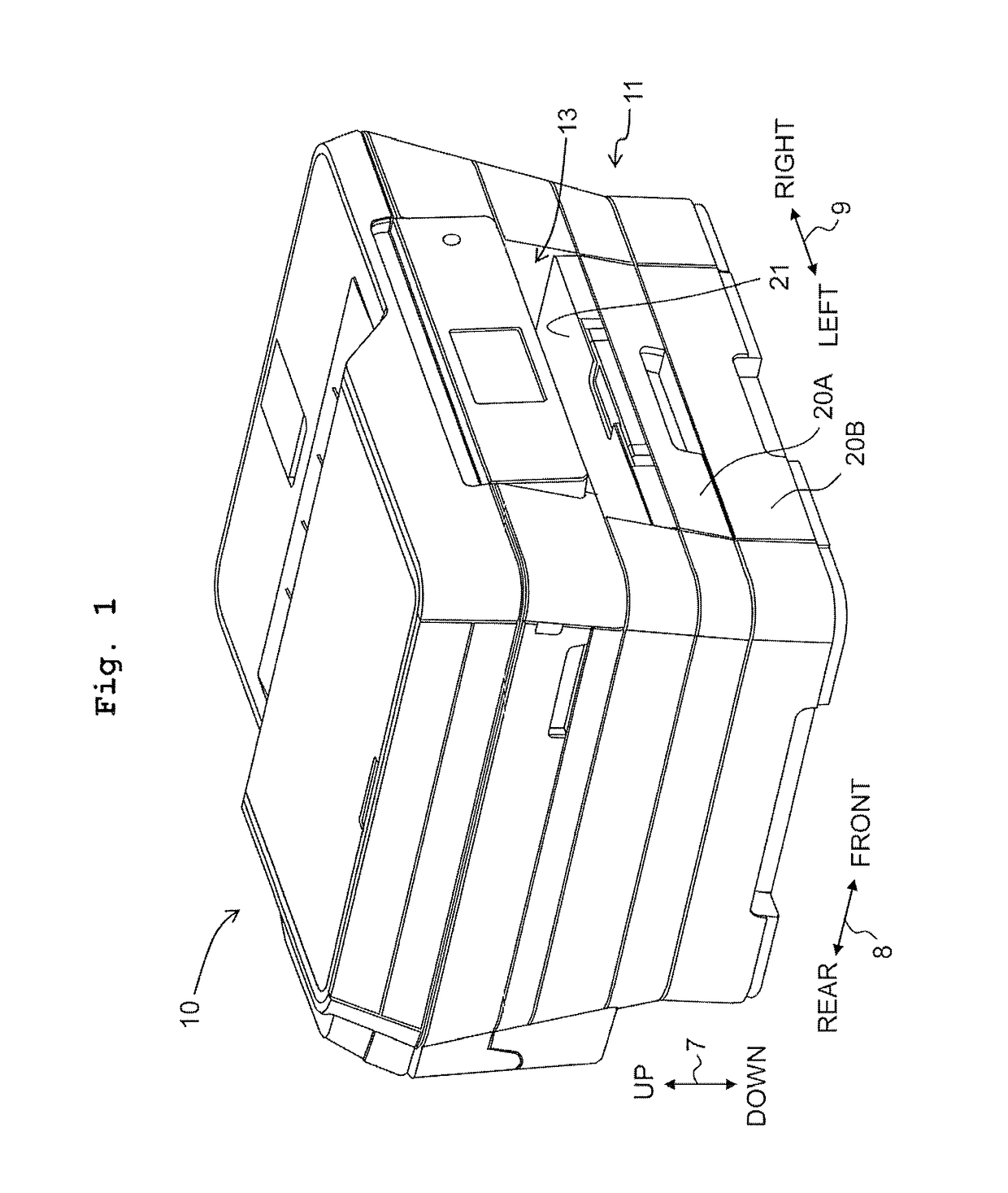
[0022]In the following, an embodiment of the present teaching will be described, with reference to the drawings. Note that, however, the embodiment described below is merely an example of the present teaching; it goes without saying that it is possible to make any appropriate change(s) in the embodiment of the present teaching without departing from the gist and / or scope of the present teaching. Further, in the following explanation, an up / down direction 7 is defined with a state in which a multi-function peripheral 10 is usably installed (a usable state; a state depicted in FIG. 1), as the reference; a front / rear direction 8 is defined, with a side on which an opening 13 of the multi-function peripheral 10 is provided is designated as the frontward side (front surface or front side); and a left / right direction 9 is defined as viewing the multi-function peripheral 10 from the frontward side (front surface).

[0023]10>

[0024]As depicted in FIG. 1, the multi-function peripheral 10 is for...


PUM


Abstract

There is provided an ink-jet printer including a conveyer, a recording head, a carriage, an ink receiver and a controller. The controller executes: receiving a recording instruction; determining an ink amount to be jetted in a flushing process; moving the carriage in a first orientation up to a returning position corresponding to the ink amount; moving the carriage in a second orientation opposite to the first orientation from the returning position to a sheet facing area; executing a flushing processing; and executing recording. The returning position is located at a first position downstream from the sheet facing area in the first orientation, under a condition that the determined ink amount is less than a threshold value; and the returning position is located at a second position downstream from the first position in the first orientation, under a condition that the determined ink amount is not less than the threshold value.

Description

CROSS REFERENCE TO RELATED APPLICATION[0001]The present application claims priority from Japanese Patent Application No. 2016-175448 filed on Sep. 8, 2016 the disclosure of which is incorporated herein by reference in its entirety.BACKGROUNDField of the Invention[0002]The present invention relates to an ink-jet printer configured to record an image, etc. on a sheet.Description of the Related Art[0003]In a conventional printer, a flushing processing for causing an ink to be jetted (discharged) from respective nozzles for the purpose of discharging a dried ink inside the nozzles, etc., is executed before executing recording of an image on a sheet. For example, there is a well-known technique for making an amount of the ink, to be jetted in the flushing processing, to be greater as a time elapsed since the ink has been jetted immediately therebefore is longer. Further, there is also a well-known technique for executing the flushing processing while causing a carriage to be moved.SUMMAR...

Claims


Application Information

Patent Timeline
Patent Type & Authority Patents(United States)
IPC IPC(8): B41J2/17B41J25/00B41J2/01
CPCB41J25/001B41J2/01B41J2/1707B41J2/16508B41J2/16526B41J23/025B41J2002/16573B41J29/02B41J29/13B41J29/38
Inventor ARAKANE, SATORU
Owner BROTHER KOGYO KK
Why Eureka
Try Eureka