Image forming apparatus configured to set a start of a feeding operation based on a value related to a rate of temperature rise for a fixing portion
a technology of fixing portion and feeding operation, which is applied in the direction of electrographic process apparatus, instruments, optics, etc., can solve the problem that the time obtained by subtracting the feeding temperature of recording material from the fpot cannot be shorter than the necessary measuring time, and achieve the effect of further shortened fpo
- Summary
- Abstract
- Description
- Claims
- Application Information
AI Technical Summary
Benefits of technology
Problems solved by technology
Method used
Image

Examples
first embodiment
(Image Forming Apparatus)
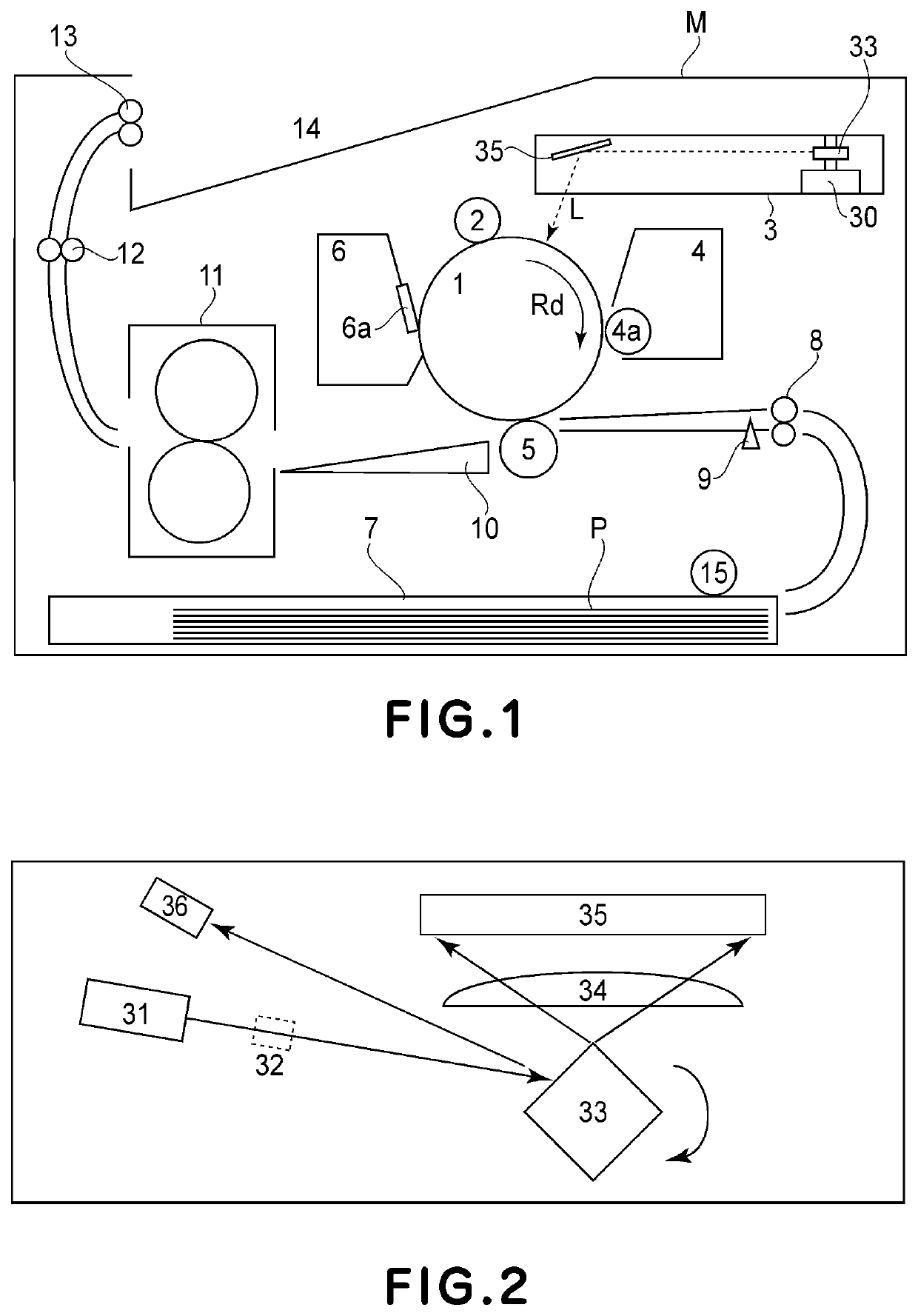
[0030]FIG. 1 is a schematic sectional view of an image forming apparatus according to an embodiment of the present invention.
[0031]In FIG. 1, a drum-shaped electrophotographic photosensitive member (hereinafter referred to as a photosensitive drum) 1, which is an image bearing member, is rotatably supported by an apparatus main assembly M and is to be rotationally driven at a predetermined process speed in an arrow Rd direction by a driving portion (unshown). At a periphery of the photosensitive drum 1 a charging device 2, a scanning portion (exposure device) 3, a developing device 4, a transfer device (transfer portion) 5 and a cleaning device 6 are successively provided in a rotation direction of the photo drum 1. The scanning portion 3 includes a scanner motor 30, a polygon mirror 33, and a reflecting mirror 35. The developing device 4 includes a developing roller 4a. The cleaning device 6 includes a cleaning blade 6a.
[0032]These members constitute an im...
second embodiment
[0084]An image forming apparatus of Second Embodiment has substantially the same constitution and operation as those in First Embodiment. This embodiment is characterized in that a control temperature at which the recording material at the fixing portion is heat-controlled is increased in the case where a measurement result for the N-th print instruction stored in the storing portion is lowered from a measurement result for the (N−1)-th print instruction stored in the storing portion by more than a first thermistor.
[0085]There is a case that a difference occurs between a temperature rising rate measurement result for the (N−1)-th print instruction (last power state) and a temperature rising rate measurement result for the N-th print instruction (current power state) in the image forming apparatus of First Embodiment. This is because as described above, the power supplied to the image forming apparatus is different depending on the voltage of the commercial voltage source. An ideal v...
third embodiment
[0101]An image forming apparatus of Third Embodiment has substantially the same constitution and operation as those in Second Embodiment. This embodiment is characterized in that sheet feeding start timing for the N-th print instruction is changed depending on whether or not an elapsed time from the (N−1)-th print instruction to the N-th print instruction is shorter than a second threshold (threshold β).
[0102]There is a possibility that a difference between a temperature rising rate measurement result for the (N−1)-th print instruction (last power state) and a temperature rising rate measurement result for the N-th print instruction (current power state) becomes larger with a longer elapsed time from the (N−1)-th print instruction to the N-th print instruction (FIG. 14). For that reason, with a longer elapsed time, the sheet is fed at short sheet feeding start timing in the high power state although the power state is changed to the lower power state and there is a possibility that ...
PUM
 Abstract
Description
Claims
Application Information
 - R&D
- Intellectual Property
- Life Sciences
- Materials
- Tech Scout
- Unparalleled Data Quality
- Higher Quality Content
- 60% Fewer Hallucinations
Browse by: Latest US Patents, China's latest patents, Technical Efficacy Thesaurus, Application Domain, Technology Topic, Popular Technical Reports.
© 2025 PatSnap. All rights reserved.Legal|Privacy policy|Modern Slavery Act Transparency Statement|Sitemap|About US| Contact US: help@patsnap.com