Image recording apparatus

a recording apparatus and image technology, applied in the direction of power drive mechanism, spacing mechanism, printing, etc., can solve the problems of paper jam, error in determining that the printer is jammed, etc., and achieve the effect of reducing the time of image recording

Active Publication Date: 2020-08-04
BROTHER KOGYO KK
View PDF2 Cites 0 Cited by
  • Summary
  • Abstract
  • Description
  • Claims
  • Application Information

AI Technical Summary

Benefits of technology

[0008]An object of the present disclosure is to provide an image recording apparatus that is capable of executing a velocity obtaining operation for obtaining carriage velocity data during movement of a carriage at appropriate timing depending on each recording mode.
[0010]When compared to the second recording mode, the first recording mode having a slower carriage velocity typically takes a longer time for image recording and uses a larger amount of liquid discharged on the recording medium, thus easily causing a paper jam. The first recording mode is thus required to give priority to the accuracy of the threshold value over the reduction of FPOT. In view of the above, the velocity obtaining operation for the first recording mode is executed in the warm-up time. This allows the threshold value for the first recording mode to be set accurately. The velocity obtaining operation for the second recording mode is executed in any other time than the warm-up time. In that case, the time after the recording command is received until image recording is started can be shortened in the second recording mode, thus reducing the FPOT. Accordingly, the velocity obtaining operation is executed at appropriate timing depending on each recording mode.

Problems solved by technology

The printer may thus erroneously determine that the printer is jammed.
When compared to the second recording mode, the first recording mode having a slower carriage velocity typically takes a longer time for image recording and uses a larger amount of liquid discharged on the recording medium, thus easily causing a paper jam.

Method used


Image

  • Image recording apparatus
  • Image recording apparatus
  • Image recording apparatus

Examples


first embodiment

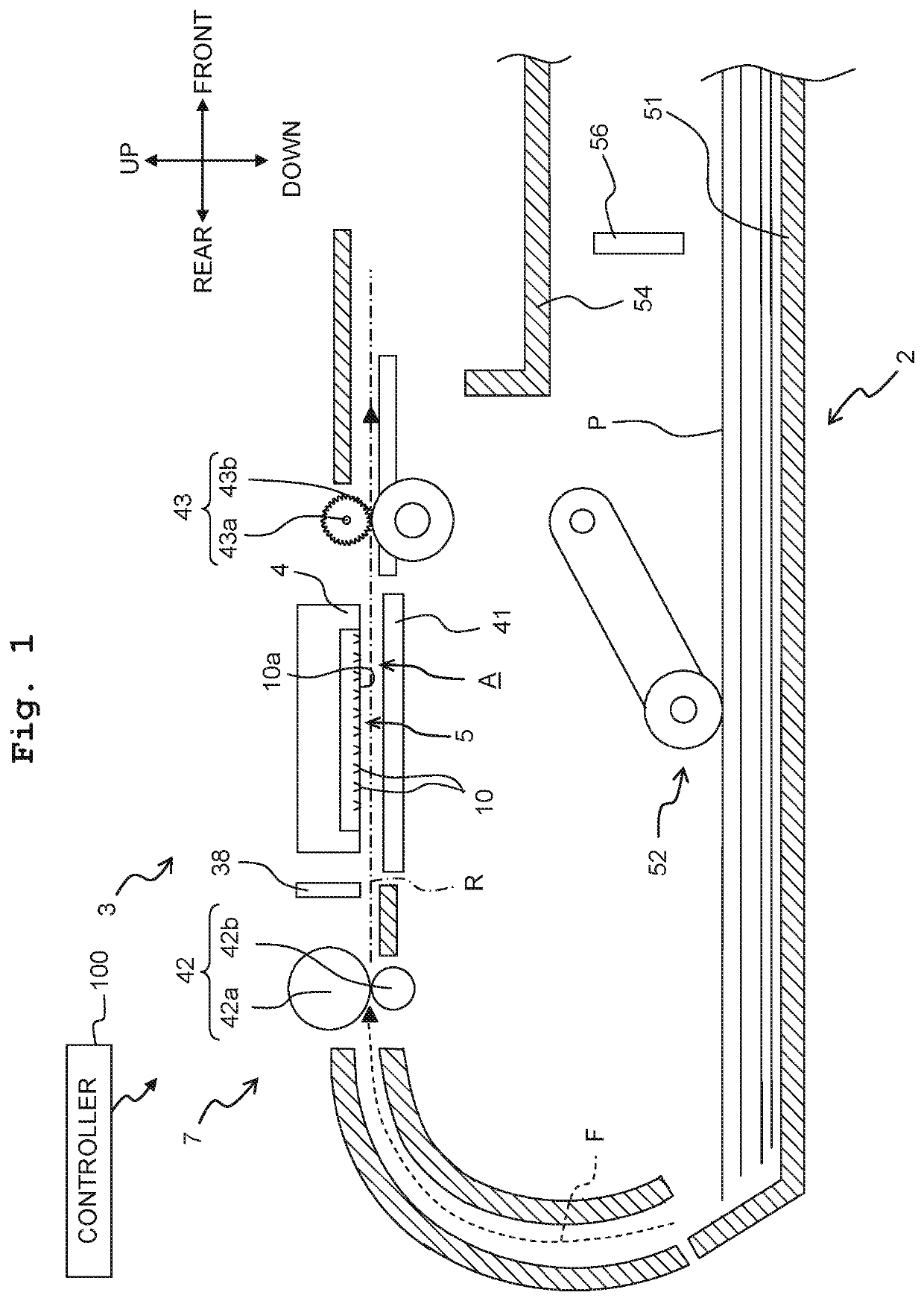
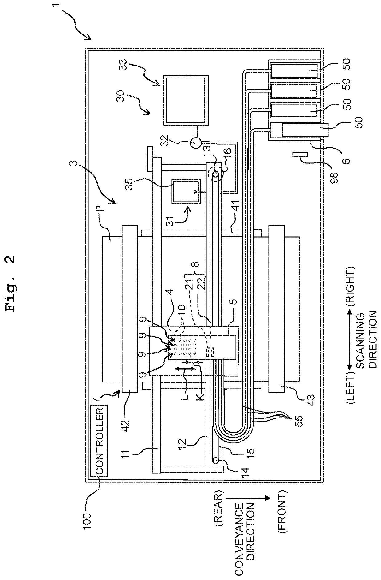
[0020]In the following, an image recording apparatus is explained by using an ink-jet printer 1 as an example. A front-rear direction, left-right direction, and up-down direction which are orthogonal to each other are defined as depicted in FIGS. 1 and 2. As depicted in FIG. 1, the printer 1 includes a feeder 2, a recording unit 3, a controller 100, and the like.

[0021]The feeder 2 includes a feed tray 51 that accommodates a sheet P as a recording medium, a pick up roller 52 provided above the feed tray 51, and a feed route F through which the sheet P passes. The feed route F curves upward from an upper end of a rear wall of the feed tray 51 and reaches a conveyance roller pair 42 described below. When the controller 100 controls and drives a feed motor 53 (see FIG. 4A), the pickup roller 52 picks up each sheet P from the feed tray 51 one by one. The sheet P picked up by the pickup roller 52 is supplied to the recording unit 3 through the feed route F.

[0022]A remaining sheet detectio...

second embodiment

[0095]A second embodiment is explained below. In the second embodiment, bidirectional recording is used to record an image, wherein the recording pass is executed both when the carriage 4 moves toward one side (rightward) in the scanning direction and when the carriage 4 moves toward the other side (leftward) in the scanning direction. Thus, in the second embodiment, the return operation is not executed between two consecutive recording passes. Here, for example, the driving load on the carriage 4 during rightward movement of the carriage 4 may be different from that during leftward movement of the carriage 4. As described above, for example, the ink supply tubes 55 extend leftward from the connection portion with the head 5, turn to change the extending direction on the left of the head 5, extend rightward, and are connected to the holder 6. In that configuration, the load from the ink supply tubes 55 when the carriage 4 moves from the left end to the right end in the scanning dire...

third embodiment

[0106]A third embodiment is explained below. In the third embodiment, when a difference between a current temperature measured by the temperature sensor 98 and a temperature mapped to a threshold value stored in the threshold value table 104a is equal to or more than a predefined value, the velocity obtaining operation and the setting of the threshold value for the high velocity recording mode are not executed. Instead, when the recording processing is executed using the high velocity recording mode, and when a difference between the current temperature measured by the temperature sensor 98 and a temperature measured by the temperature sensor 98 in the last velocity obtaining operation is equal to or more than the predefined value, a threshold value set based on the last velocity obtaining operation is corrected, and the corrected threshold value is used in the recording pass. The threshold value 104a of the non-volatile memory 104 stores two temperatures measured by the temperature...


PUM


Abstract

There is provided an image recording apparatus including a carriage, a head, a velocity sensor, and a controller. The controller obtains velocity data of the carriage from the velocity sensor, determines a threshold value based on the velocity data, records an image on a recording medium, and suspends a recording pass when the controller has determined that a velocity indicated by the velocity data is lower than a velocity corresponding to the threshold value. The controller can execute a first recording mode and a second recording mode in which the velocity of the carriage is faster than that of the first recording mode. The velocity data for the first recording mode is obtained in a warm-up time after a recording command is received until recording of the image is started. The velocity data for the second recording mode is obtained in other time other than the warm-up time.

Description

CROSS REFERENCE TO RELATED APPLICATION[0001]The present application claims priority from Japanese Patent Application No. 2018-124340 filed on Jun. 29, 2018, the disclosure of which is incorporated herein by reference in its entirety.BACKGROUNDField of the Invention[0002]The present disclosure relates to an image recording apparatus.Description of the Related Art[0003]There is publicly known, as an image recording apparatus, a serial-type printer in which ink is discharged from a printing head on a sheet while a carriage carrying the printing head moves in a scanning direction. The above printer determines, in printing, whether a carriage velocity is lower than a threshold value set in advance. When the printer has determined that the carriage velocity is lower than the threshold value, the printer determines that a jam is caused in the printer and the printer stops movement of the carriage.[0004]The carriage velocity depends, for example, on the change in environment where the print...

Claims


Application Information

Patent Timeline
Patent Type & Authority Patents(United States)
IPC IPC(8): B41J2/045B41J25/00
CPCB41J25/001B41J2/04528B41J2/04586B41J2/04563B41J2/04551B41J2/16517B41J19/207B41J19/205
Inventor ARAKANE, SATORUKAWAMOTO, KENJIITO, TSUYOSHI
Owner BROTHER KOGYO KK
Why Eureka
Try Eureka