Holder for fastening a component on an internal combustion engine, a bearing bush for such a holder, and a fuel injection system

a technology for internal combustion engines and components, applied in the direction of springs/dampers, machines/engines, mechanical equipment, etc., can solve the problem of fuel distributors being excited to vibrations, and achieve the effect of reducing noise emissions and improving vibration damping

Active Publication Date: 2018-10-02
ROBERT BOSCH GMBH
View PDF16 Cites 0 Cited by
  • Summary
  • Abstract
  • Description
  • Claims
  • Application Information

AI Technical Summary

Benefits of technology

[0010]The inner bush part and the outer bush part may advantageously be made of two metal sleeves lying inside each other, which are laid into a mold. Subsequently, a plastic, especially an elastomeric plastic, may be introduced into the mold, so that an intermediate space between the inner bush part and the outer bush part is filled up. By special production methods, such as vulcanizing, it may be achieved in an advantageous manner that the material for the damping element, particularly the elastomeric partition, combines integrally with the metal surfaces. After release from the mold, the bush parts and the damping element, that are firmly connected to one another, thus form a component made up of the metallic bush parts and the damping element. Since the contact areas between the metallic materials and the elastically deformable material of the damping element are firmly connected to each other, the joints in this embodiment have a particularly great resistance to wear. In addition, the elastically deformable damping element is at first not under prestressing. Even in the mounted state, the damping element does not necessarily have to absorb screw forces since the frictional connection between a fastening arrangement, particularly a screw, is able to be guided onto the internal combustion engine completely via the inner bush part.
[0011]The damping element advantageously prevents a metallic contact between the inner bush part and the outer bush part, so that a complete elastic insulation is ensured between the component, particularly the fuel distributor, and the internal combustion engine. An insulating effect in all spatial directions may be achieved in that the material for the elastically deformable damping element has great material damping. Thereby, even at a very small layer thickness of the damping element, which may be, for example, in a range of a few tenths of a millimeter, a clear insulation effect may be achieved. Consequently, a layer thickness of the elastically deformable damping element of less than 1 mm may be specified.
[0012]Thus, it is advantageous that the damping element is connected integrally with the inner bush part and the damping element is connected integrally with the outer bush part. In this instance, it is also advantageous that the damping element is connected to the inner bush part by vulcanizing and that the damping element is connected to the outer bush part by vulcanizing. In an advantageous manner, the damping element may be developed on the basis of at least one elastomer or a rubber. In this instance, a small layer thickness is able to be implemented.
[0011]The damping element advantageously prevents a metallic contact between the inner bush part and the outer bush part, so that a complete elastic insulation is ensured between the component, particularly the fuel distributor, and the internal combustion engine. An insulating effect in all spatial directions may be achieved in that the material for the elastically deformable damping element has great material damping. Thereby, even at a very small layer thickness of the damping element, which may be, for example, in a range of a few tenths of a millimeter, a clear insulation effect may be achieved. Consequently, a layer thickness of the elastically deformable damping element of less than 1 mm may be specified.
[0014]It is also advantageous that the inner bush part and the outer bush part have supporting contours adapted to each other at the continuous recess. Thereby, in addition, axial cross section changes are able to be specified, by which the axial contact surfaces between the metallic bush parts and the damping element configured as a layer, particularly as an elastomer layer, increase in total. Because of this, the protection of the damping element from the shearing wear, amid the initiation of operating forces, may be further improved.
[0015]The supporting contours may be embodied annularly about the longitudinal axis of the bearing bush. The supporting contours adapted to each other may, in this case, advantageously be a groove and a rib or disk assigned to the groove and / or shoulders assigned to each other. The groove, rib, disk or the shoulders are in this case may be configured annularly on the bush parts. In this instance, a plurality of such supporting contours may be provided in the longitudinal direction. Meanwhile, the supporting contours may be configured differently or in repetitive fashion.
[0011]The damping element advantageously prevents a metallic contact between the inner bush part and the outer bush part, so that a complete elastic insulation is ensured between the component, particularly the fuel distributor, and the internal combustion engine. An insulating effect in all spatial directions may be achieved in that the material for the elastically deformable damping element has great material damping. Thereby, even at a very small layer thickness of the damping element, which may be, for example, in a range of a few tenths of a millimeter, a clear insulation effect may be achieved. Consequently, a layer thickness of the elastically deformable damping element of less than 1 mm may be specified.
[0011]The damping element advantageously prevents a metallic contact between the inner bush part and the outer bush part, so that a complete elastic insulation is ensured between the component, particularly the fuel distributor, and the internal combustion engine. An insulating effect in all spatial directions may be achieved in that the material for the elastically deformable damping element has great material damping. Thereby, even at a very small layer thickness of the damping element, which may be, for example, in a range of a few tenths of a millimeter, a clear insulation effect may be achieved. Consequently, a layer thickness of the elastically deformable damping element of less than 1 mm may be specified.
[0011]The damping element advantageously prevents a metallic contact between the inner bush part and the outer bush part, so that a complete elastic insulation is ensured between the component, particularly the fuel distributor, and the internal combustion engine. An insulating effect in all spatial directions may be achieved in that the material for the elastically deformable damping element has great material damping. Thereby, even at a very small layer thickness of the damping element, which may be, for example, in a range of a few tenths of a millimeter, a clear insulation effect may be achieved. Consequently, a layer thickness of the elastically deformable damping element of less than 1 mm may be specified.
[0021]Numerous advantages may thus be achieved.
[0022]The noise transmission from a fuel distributor into the add-on structure, especially into the internal combustion engine, decreases in response to a rigid screw joint.
[0023]Vibrations of the fuel distributor may be damped more greatly, whereby the sound radiation from the surface of the fuel distributor diminishes.
[0024]The vibrational stressing of the fuel distributor and of the high-pressure injector valves based on the vibrational stressing of the internal combustion engine decreases, since the vibrational transmission in this direction is also being damped. Thereby advantages are created with respect to the configuration and reliability of these components.
[0025]Because of the vulcanization process, the elastomeric layer or a compatible layer, of which the damping element is made, adheres particularly well to the metallic bush parts. Thereby tangential relative motions are avoided. Furthermore, the risk of the formation of a tear on the contact surface and the risk of abrasion are reduced.

Problems solved by technology

In operation, the problem arises that the fuel distributor may be excited to vibrations in the audible frequency range.
Above all, this may happen because of noise sources in the fuel injectors that are components of a fuel injection system.
The structure-borne noise, in this instance, spreads from the fuel injectors, via rail bucket tappets, the fuel distributor and the holder to the externally-mounted structure, from where disturbing noises may be radiated which, under certain circumstances, may even penetrate into the interior of the vehicle.

Method used


Image

  • Holder for fastening a component on an internal combustion engine, a bearing bush for such a holder, and a fuel injection system
  • Holder for fastening a component on an internal combustion engine, a bearing bush for such a holder, and a fuel injection system
  • Holder for fastening a component on an internal combustion engine, a bearing bush for such a holder, and a fuel injection system

Examples


Embodiment Construction

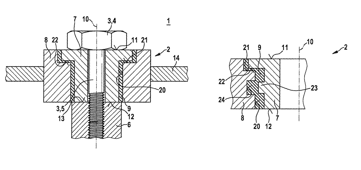
[0038]FIG. 1 shows a holder 1 having a bearing bush 2 in a schematic sectional representation in excerpted form, corresponding to a first exemplary embodiment of the present invention.

[0039]Holder 1 has fastening arrangement 3, which in this exemplary embodiment is configured as a screw 3. Fastening arrangement 3 has a head 4 and a bolt (screw bolt) 5. Using fastening arrangement 3, bearing bush 2 is fastened to an add-on structure 6. Add-on structure 6 may be an internal combustion engine 6, especially a cylinder head 6 of an internal combustion engine 6, in this exemplary embodiment.

[0040]Bearing bush 2 has an inner bush part 7 and an outer bush part 8. Furthermore, bearing bush 2 has an elastically deformable damping element 9.

[0041]Bush parts 7, 8 are each formed of a metallic material. In this context, bush parts 7, 8 may also be formed of the same metallic material.

[0042]The elastically deformable damping element 9 may be made of a rubber, that is, an elastomeric layer. Dampin...


PUM


Abstract

A bearing bush is for a holder, which is for fastening a component, particularly of a fuel distributor, to an add-on structure. The bearing bush has an inner bush part, which is made of a metallic material, and an outer bush part, which is made of a metallic material, and an elastically deformable damping element. The outer bush part has a continuous recess, in which the inner bush part is situated. The damping element is situated between the inner bush part and the outer bush part. A holder having such a bearing bush is also specified. In addition, a fuel-injection system having a fuel distributor and at least one holder is specified, which is used for fastening the fuel distributor on an internal combustion engine.

Description

FIELD OF THE INVENTION[0001]The present invention relates to a holder for fastening at least one component, especially a fuel distributor, on an internal combustion engine. The present invention especially relates to the field of fuel injection systems of internal combustion engines.BACKGROUND INFORMATION[0002]An insulating holder for connecting a common rail of a fuel injection system for the direct injection of fuel to an internal combustion engine is discussed in U.S. Pat. No. 7,682,117 B2. Clamping elements are provided, which face each other, and are used as prestressing limiters and have a damping ring made of an elastomer assigned to them in each case. In the fastening, the axial prestressing excursion is limited via a gap between the clamping elements.[0003]In the holder of U.S. Pat. No. 7,682,117 B2, it is therefore possible to use two annular elastomeric components in combination with two metal sleeves for the damping, while the prestressing is limited. The limitation is a...

Claims


Application Information

Patent Timeline
Patent Type & Authority Patents(United States)
IPC IPC(8): F02M61/14F02M55/02F16F1/38F02F11/00
CPCF16F1/38F02M55/025F02M61/14Y10T403/451F02M2200/306F02M2200/857
Inventor REHWALD, ANDREASMAESS, MATTHIASGUENGOER, GOEKHAN
Owner ROBERT BOSCH GMBH
Why Eureka
Try Eureka