
Screen grid insulated concrete form panel system and method for construction and building

a technology of concrete form panels and grids, applied in the field of concrete forms, can solve the problems of difficult and/or time-consuming stacking or otherwise assembling, high processing costs, and labor-intensive, and achieve the effect of reducing building costs and building costs

Inactive Publication Date: 2018-10-02
MONTOYA ROBERT
View PDF21 Cites 0 Cited by
  • Summary
  • Abstract
  • Description
  • Claims
  • Application Information

AI Technical Summary

Benefits of technology

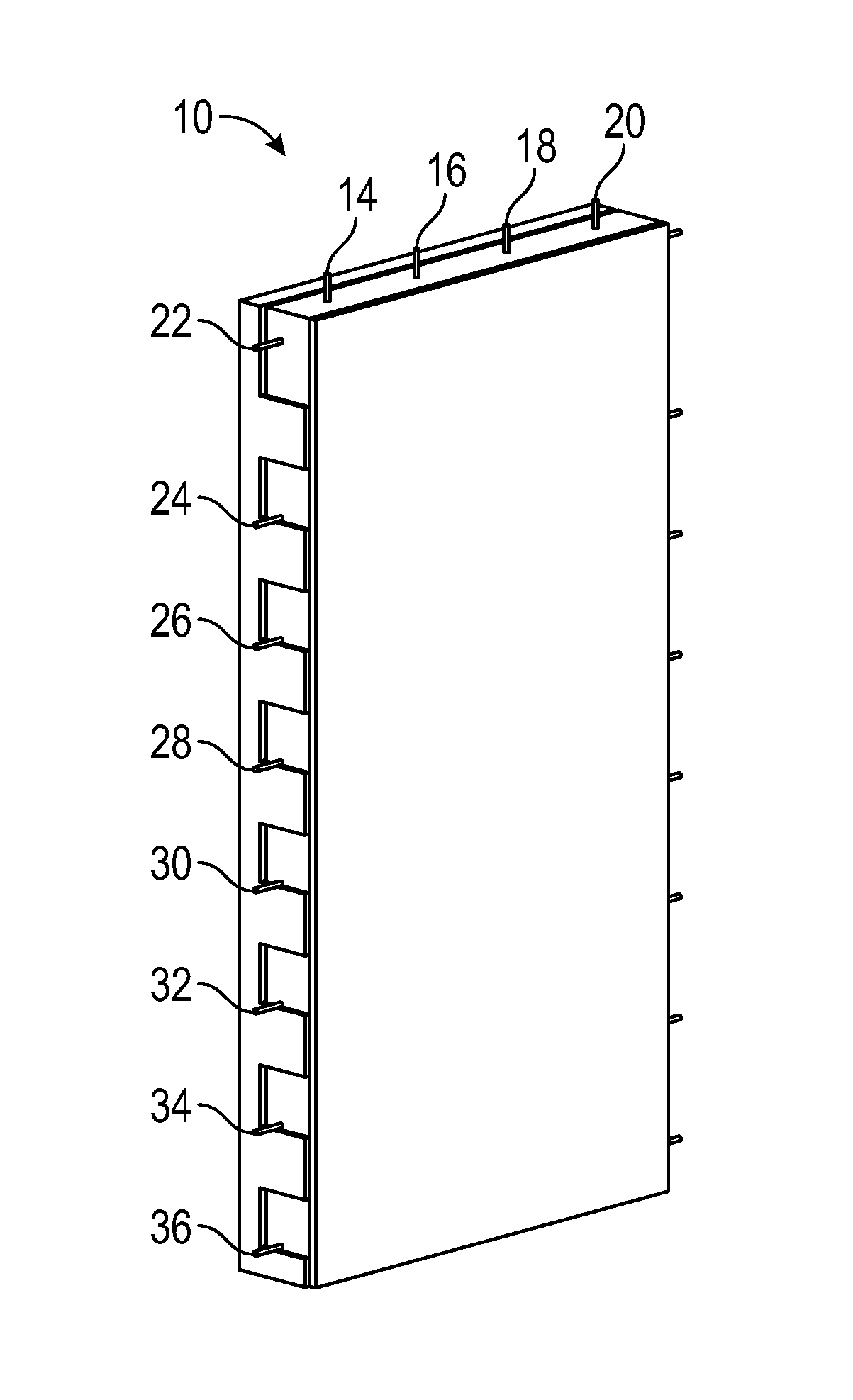
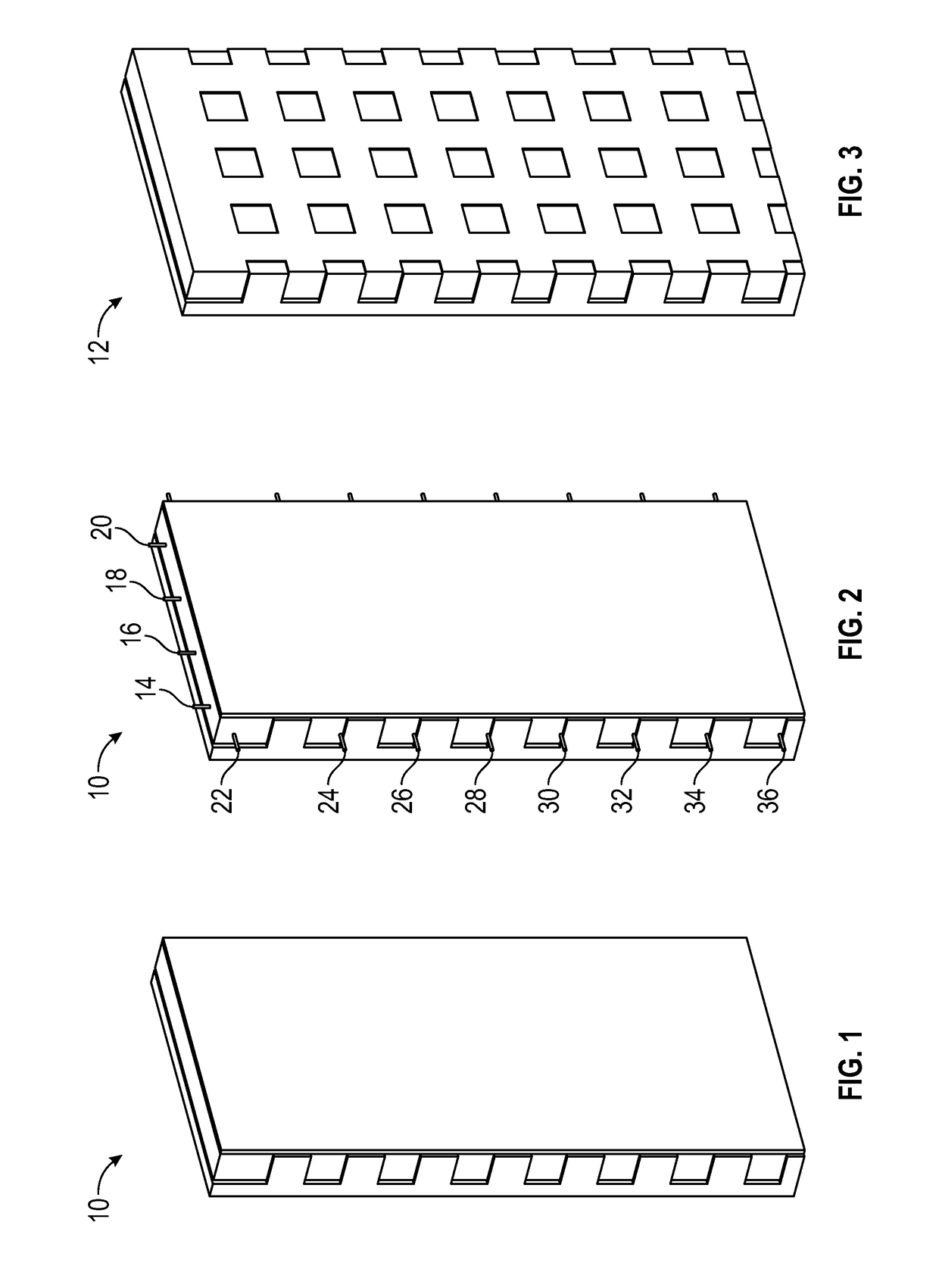
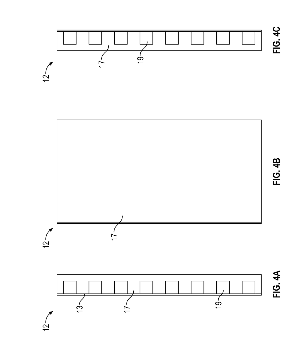
[0010]The aforementioned aspects and other objectives and advantages can now be achieved as described herein. In one example embodiment, a screen grid insulated concrete form panel system can be implemented, which uniquely places the filled concrete thermal mass of the wall system on the interior face of the wall system and expanded polystyrene insulation on the exterior side of the wall system, resulting in superior thermal stability and isolation of the interior climate of the structure built with the system. Such a system creates a thermal break between the exterior of the structure and the concrete thermal mass. Such a system allows for a thermal bridge between the interior of the structure and the concrete thermal mass. The system's interior panel can include a glass mat sheathing that permits thermal transfer into and out of the encapsulated concrete thermal mass. The result is a highly stable interior air temperature that is not affected by fluctuations in the exterior climate. The concrete thermal mass stabilizes the interior air temperature in a tight range by absorbing and dissipating heat.
[0012]In yet another example embodiment, a screen grid insulated concrete form panel system can be implemented, which includes a glass mat sheathing sheet for an interior finish substrate in the panel itself, which serves as a form for the concrete and eliminates the need for interior drywall application. In addition to eliminating this construction step, it results in a minimum, for example, one hour fire rating with respect to the wall system. The glass mat sheathing can be installed with an offset in order to assist with the alignment of the subsequent panel which also has, for example, a similar offset. Such a configuration can enable the panels to be quickly stood up and aligned.
[0013]In still another example embodiment, a screen grid insulated concrete form panel system can be implemented, which eliminates the need for stacking small blocks to attain a standard ceiling height. The dimensions of such system allow it to be compatible with other building systems commonly used in construction. A large lightweight panel, for example, offers significant advantages over conventional insulated form products including ease of installation, thermal performance, and overall cost of construction since the panels are larger and more complete than conventional insulated concrete forms. The system greatly simplifies the process of insulated concrete form construction making it cost competitive with conventional wood frame construction.
[0015]In still another example embodiment, a screen grid insulated concrete form panel system that uniquely can be produced and installed on the job site drastically reducing the cost of building with the system. Expanded polystyrene panels can be trimmed and glue attached to, for example, the glass mat sheathing sheet. Typically insulated concrete forms are produced in a large expensive centralized factory then inefficiently transported to remote job sites for installation. Producing the large panels on site eliminates one transportation step and one production step drastically reducing the cost of building with the system.

Problems solved by technology

Traditional systems, however, have several drawbacks including the time required to erect the forms, the time for the concrete to cure, and the time to take down the forms making the process expensive and labor-intensive.
The problem with known forms, however, is that they are often difficult and / or time consuming to stack together or otherwise assemble.
Further, known concrete forms for use in the construction of buildings and the like do not incorporate and thus provide an interior surface which can be quickly, easily, and inexpensively finished.

Method used


Image

  • Screen grid insulated concrete form panel system and method for construction and building
  • Screen grid insulated concrete form panel system and method for construction and building
  • Screen grid insulated concrete form panel system and method for construction and building

Examples


Embodiment Construction

[0022]The particular values and configurations discussed in these non-limiting examples can be varied and are cited merely to illustrate at least one embodiment and are not intended to limit the scope thereof.

[0023]The embodiments will now be described more fully hereinafter with reference to the accompanying drawings, in which illustrative embodiments of the invention are shown. The embodiments disclosed herein can be embodied in many different forms and should not be construed as limited to the embodiments set forth herein; rather, these embodiments are provided so that this disclosure will be thorough and complete, and will fully convey the scope of the invention to those skilled in the art. Like numbers refer to identical, like or similar elements throughout, although such numbers may be referenced in the context of different embodiments. As used herein, the term “and / or” includes any and all combinations of one or more of the associated listed items.

[0024]The terminology used h...


PUM


Abstract

A concrete form panel system and method includes a screen grid insulated concrete form panel for use in a wall system. The screen grid insulated concrete form panel includes a filled concrete thermal mass of the wall system located on an interior face of the wall system with expanded polystyrene insulation on an exterior side of the wall system, which results an enhanced thermal stability and isolation of an interior climate of a structure constructed utilizing the wall system.

Description

CROSS-REFERENCE TO PROVISIONAL APPLICATION[0001]This nonprovisional patent application claims the benefit under 35 U.S.C. § 119(e) and priority to U.S. Provisional Patent Application Ser. No. 62 / 277,122 filed on Jan. 11, 2016, entitled “Screen Grid Insulated Concrete Form Panel System and Method for Construction and Building,” which is incorporated herein by reference in its entirety.TECHNICAL FIELD[0002]Embodiments are related to concrete forms composed of an insulative material. Embodiments also relate to a screen grid insulated concrete form panel for use in construction and buildings.BACKGROUND[0003]Concrete forms are utilized as a framework for the construction of concrete structures, such as the walls or floors of a building. Traditional form systems typically entail setting up two spaced apart form panels and pouring concrete into the space created between the panels. After the concrete hardens, the forms are removed, leaving the cured concrete wall. Traditional systems, howe...

Claims


Application Information

Patent Timeline
Patent Type & Authority Patents(United States)
IPC IPC(8): E04G11/06E04B2/86
CPCE04G11/06E04B2/8611E04B2103/02E04B2002/8682E04B2002/867
Inventor MONTOYA, ROBERT
Owner MONTOYA ROBERT
Learn More