Linear electrical machine/generator with segmented stator for free piston engine generator

a generator and linear technology, applied in the direction of machines/engines, magnetic circuits characterised by magnetic materials, magnetic circuit shapes/forms/construction, etc., can solve the problems of complex mechanical and expensive mechanical, and achieve the effect of high efficiency and high efficiency of electrical power conversion

Active Publication Date: 2018-09-11
LIBERTINE FPE
View PDF58 Cites 2 Cited by
  • Summary
  • Abstract
  • Description
  • Claims
  • Application Information

AI Technical Summary

Benefits of technology

The present invention is a linear electrical machine that is designed to improve the efficiency of combustion and electrical power conversion in an engine. It includes a cylinder housing with cooling channels, a piston with a uniform cross section, and a ratio of piston length to piston diameter that matches the power output of the combustion chamber. The piston has a high electrical machine control force acting on low piston mass for more consistent combustion process control, and avoids the use of costly rare earth magnetic materials in the piston and complex design interfaces between combustion and electrical power generation mechanisms in the engine. The invention also provides an axial flux electrical machine topology with minimal eddy current losses, higher efficiency, and improved piston motion control compared to transverse flux configurations. The piston has a piston crown to protect the core and spacer elements from the effects of combustion, and may also have a concave surface to reduce heat loss at top dead centre. The piston crown is constructed from a lightweight, temperature resistant and insulating material, and may also have an oxidation catalyst material to improve the consistency and completenness of combustion in the combustion chamber.

Problems solved by technology

However, the piston is constructed from a solid piece of material that is permeable to magnetic flux and is necessarily very short relative to the length of the cylinder so that it may induce the flux changes as it passes through the second coil.
This change in diameter necessitates complex and expensive mechanical solutions to seal each combustion chamber, and to ensure that these are coaxially aligned with each other and with the axis of the intervening electrical machine.

Method used


Image

  • Linear electrical machine/generator with segmented stator for free piston engine generator
  • Linear electrical machine/generator with segmented stator for free piston engine generator
  • Linear electrical machine/generator with segmented stator for free piston engine generator

Examples


Embodiment Construction

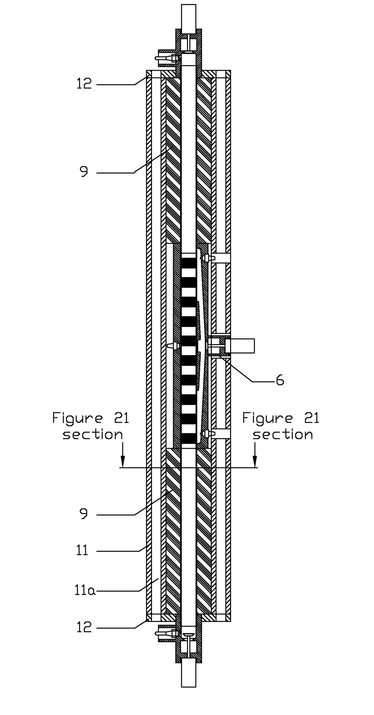
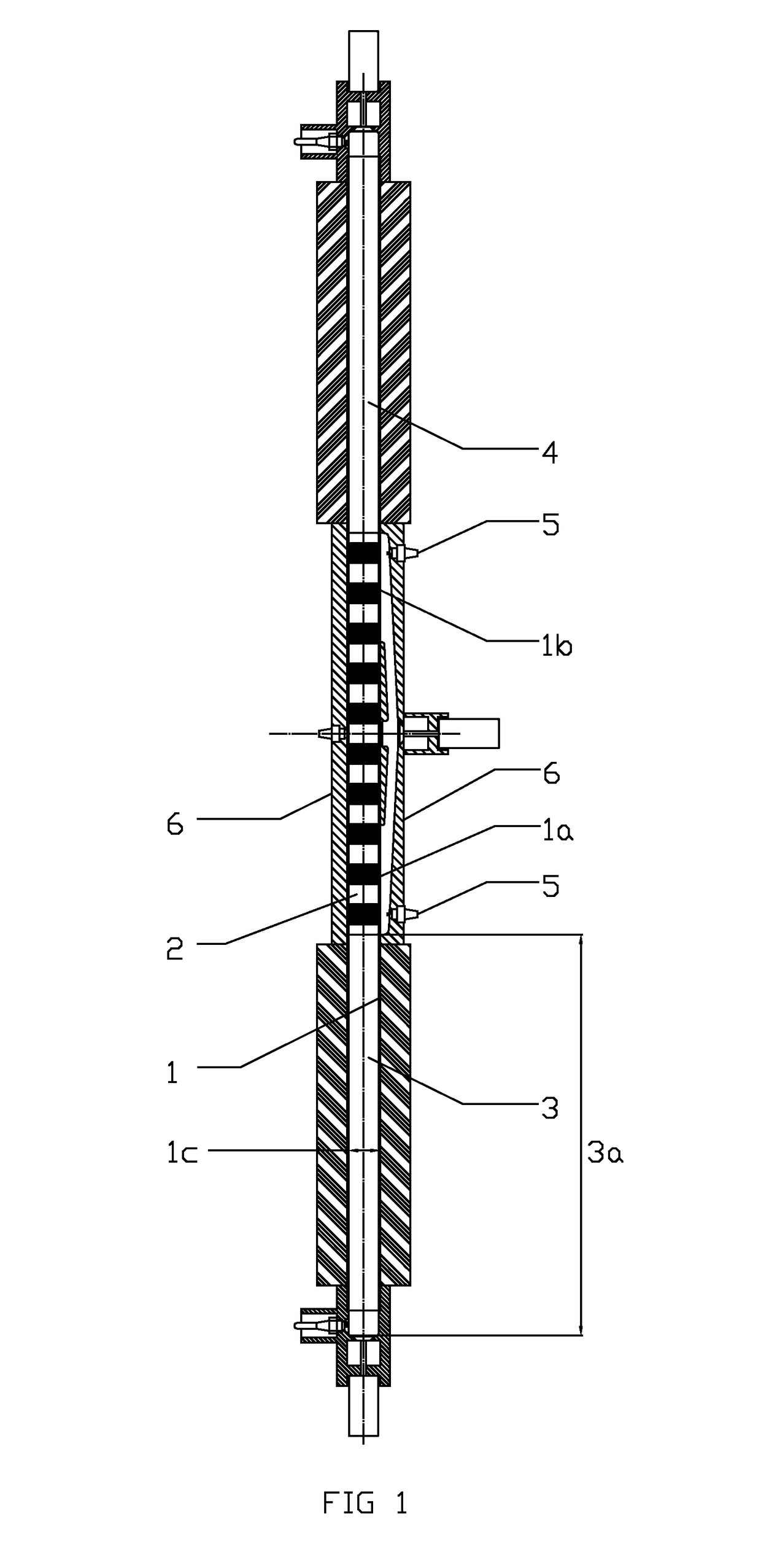
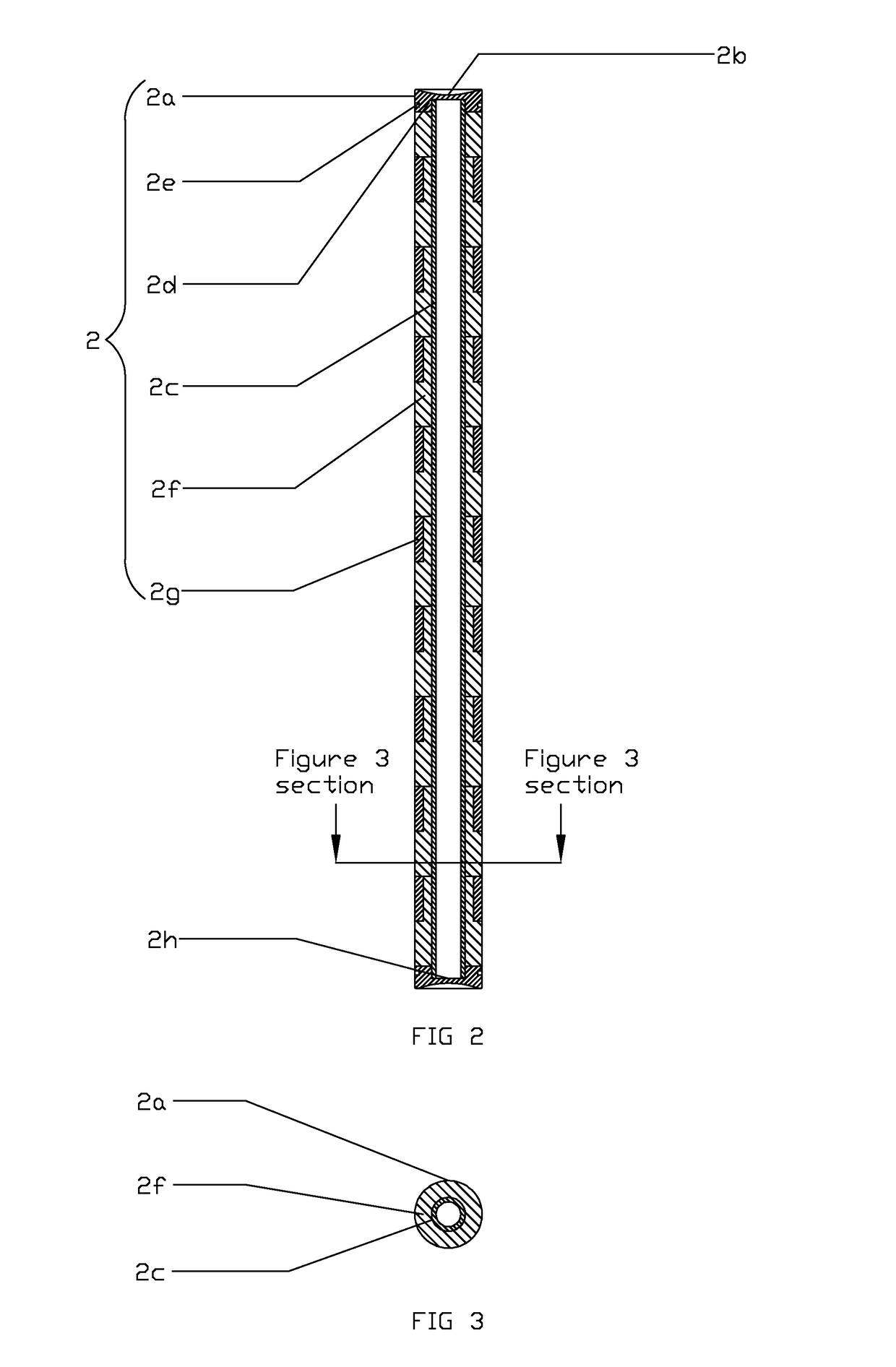
[0044]In these figures and specification, the following labels are used:[0045]1—Cylinder bore surface layer[0046]1a—First intake port aperture[0047]1b—Second intake port aperture[0048]1c—Cylinder bore[0049]2—Piston[0050]2a—Piston outer surface[0051]2b—Piston end surface[0052]2c—Piston shaft[0053]2d—Piston crown[0054]2e—Lubrication control feature[0055]2f—Magnetically permeable piston core element[0056]2g—Non-permeable piston spacer element[0057]2h—Piston shaft end[0058]2i—Piston shaft cap[0059]3—First combustion chamber[0060]3a—First combustion chamber height[0061]4—Second combustion chamber[0062]5—Fuel injection means[0063]5a—Fuel[0064]6—Intake means[0065]6a—Intake sliding port valve apertures[0066]6b—Air intake[0067]6c—Intake valve[0068]6d—Intake valve actuator[0069]6e—Intake charge compressor[0070]6f—Intake manifold[0071]6g—Intake valve recess[0072]6h—Intake channel[0073]7—Exhaust means[0074]7a—Cylinder head[0075]7b—Exhaust valve[0076]7c—Exhaust valve actuator[0077]7d—Exhaust man...


PUM

PropertyMeasurementUnit
Pressureaaaaaaaaaa
Pressureaaaaaaaaaa
Frequencyaaaaaaaaaa

Abstract

A linear electrical machine comprising a movable piston, an axially segmented cylinder having least one magnetically permeable segment and a bore configured to allow the piston to move within the cylinder, a cylinder housing having a bore for receiving the segmented cylinder, and means for securing the segmented cylinder in place within the cylinder housing. This arrangement permits the construction of it free piston engine linear with improved piston position control, more consistent combustion and improved electrical conversion efficiency.

Description

CROSS REFERENCE TO RELATED APPLICATION[0001]The present application is the U.S. national stage application of International Application PCT / GB2013 / 050106, filed Jan. 18, 2013, which international application was published on Jul. 25, 2013, as International Publication WO2013 / 108034. The international Application claims priority of British Patent Application 1200889.2, filed Jan. 19, 2012, the contents of which are incorporated herein by reference in their entireties.BACKGROUND OF THE INVENTION[0002]The present invention relates to a linear electrical machine and in particular linear electrical generator for a free piston engine generator.[0003]In standard combustion engines, pistons are mechanically restrained within their cylinder as a result of being connected to a crankshaft, which is driven rotationally as a result of the reciprocating linear movement of the piston within the cylinder. In a free piston engine, however, the piston is not connected to a crankshaft, although piston...

Claims


Application Information

Patent Timeline
IPC IPC(8): F02B71/06H02K5/20H02K33/12H02K35/02H02K5/04F02B63/04H02K15/02H02K35/00H02K7/18F02B71/04H02K1/18H02K9/20H02K5/18
CPCF02B71/06F02B63/041F02B71/04H02K5/04H02K5/20H02K7/1884H02K33/12H02K35/00H02K35/02H02K15/02Y10T29/49009H02K1/185H02K5/18H02K9/20H02K5/203F02B71/00H02K7/18H02K1/18H02K1/02F02B63/04H02K2213/03
Inventor COCKERILL, SAMUEL EDWARD
Owner LIBERTINE FPE
Why Eureka
Try Eureka