
Method and system for geometric referencing of multi-spectral data

a multi-spectral data and geometric reference technology, applied in the field of image capture, can solve the problems of difficult handling, large amount of data, and inability to collect data in a certain way, and achieve the effects of reducing the frame rate, less mass amount of data generated, and increasing the frame rate of the spectral sensor

Inactive Publication Date: 2018-08-21
VLAAMSE INSTELLING VOOR TECHNOLOGISCH ONDERZOEK NV VITO
View PDF6 Cites 1 Cited by
  • Summary
  • Abstract
  • Description
  • Claims
  • Application Information

AI Technical Summary

Benefits of technology

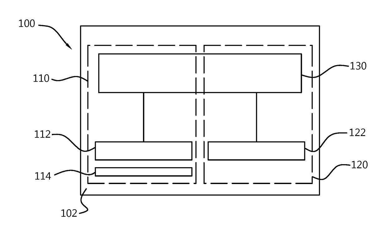
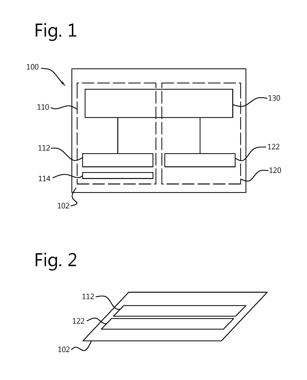
This patent describes a new design for a hyperspectral sensing device that allows for faster operation and more efficient data collection. The design includes two image sensors: a first sensor that collects spatial information and a second sensor that collects spectral information. The second sensor can operate at a lower frame rate, reducing the amount of data generated. This allows for increased frame rates for the spectral sensor, which in turn enables the use of a sensor with more wavelength channels. The second sensor can be adjusted to provide proper geometric referencing, and the first sensor can be designed to provide full spatial coverage of all relevant wavelength channels. The first sensor can also be integrated onto the same substrate as the second sensor, further improving the device's efficiency.

Problems solved by technology

This way of data collection nevertheless is not always possible, especially when the region of interest and the imaging system undergo a large relative movement with respect to each other.
When the frame rate is further increased, the known sensor device generates a large amount of data which can be difficult to handle and the registration of the spectral data with the geometric data becomes computationally more demanding.
This disadvantage can render the known sensor device less suitable for applications which require a large number of spectral channels.

Method used


Image

  • Method and system for geometric referencing of multi-spectral data
  • Method and system for geometric referencing of multi-spectral data
  • Method and system for geometric referencing of multi-spectral data

Examples


Embodiment Construction

[0036]For illustrative purposes, the invention will be described with reference to the sensing device of the aforementioned international patent application publication WO 2011 / 073430 A1, but this is done without loss of generality. The characterizing features of the present invention can be combined with features of various embodiments of the known sensing device, as described in more detail in the following description. Details of the known sensing device are omitted where this is not necessary for the understanding of the present invention; the description of WO 2011 / 073430 A1 is hereby incorporated by reference for the purpose of guiding the implementation of corresponding embodiments of the present invention.

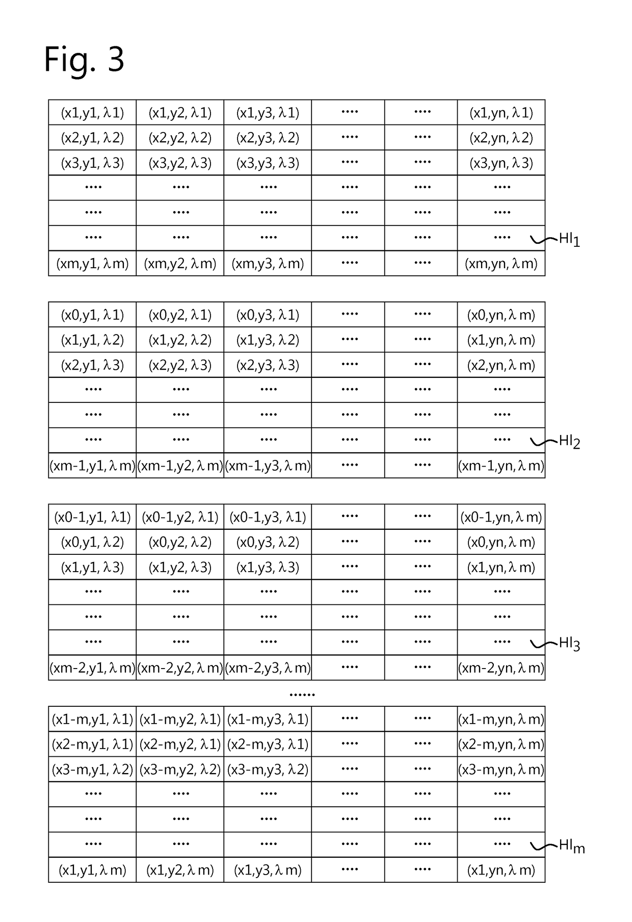
[0037]Where in the present invention reference is made to a two dimensional multi-spectral image, reference is made to an m×n pixelated image comprising information regarding one part of a region of interest imaged at one wavelength or spectral region and comprising informa...


PUM


Abstract

A sensing device for obtaining geometric referenced multi-spectral image data of a RoI in relative movement with respect to the device, the sensing device having: a first and second 2D sensor element, the device obtaining subsequent multi-spectral images during the relative motion of the Rol thus providing distinct spectral information for parts of a Rol using the first element; and providing, using the second element, an image of the Rol for generating geometric referencing information to be coupled to the distinct spectral information; each element capturing a sequence of frames at a respective frame rate. The first frame rate is higher than the second frame rate. The device generates intermediate geometric referencing information to be coupled to frames of the first sequence of frames for which no synchronous frame from the second sequence of frames is available, derived from temporally similar frames from the second sequence of frames.

Description

FIELD OF THE INVENTION[0001]The invention relates to the field of image capturing e.g. in aerial or industrial imaging. More particularly, the present invention relates to sensing systems for obtaining multi-spectral images, corresponding imaging systems and methods for using them.BACKGROUND OF THE INVENTION[0002]Hyperspectral imaging is a form of spectral imaging wherein information from across the electromagnetic spectrum is collected in many narrow spectral bands and processed. From the different spectral images that are collected, information of the objects that are imaged can be derived. For example, as certain objects leave unique spectral signatures in images which may even depend on the status of the object, information obtained by multi-spectral imaging can provide information regarding the presence and / or status of objects in a region that is imaged. After selection of a spectral range that will be imaged, as spectral images in this complete spectral range can be acquired,...

Claims


Application Information

Patent Timeline
Patent Type & Authority Patents(United States)
IPC IPC(8): G01C11/02H04N7/18B64D47/08H04N5/33B64C39/02G01J3/28
CPCG01C11/025B64C39/024B64D47/08H04N5/332H04N7/183G01J3/2823G01J2003/2826B64C2201/127B64U2101/30H04N23/11H04N7/12H04N7/18
Inventor MICHIELS, BARTDELAURE, BAVOLIVENS, STEFAN
Owner VLAAMSE INSTELLING VOOR TECHNOLOGISCH ONDERZOEK NV VITO
Learn More