Driving device

a technology of a driving device and a control device, which is applied in the direction of electric variable regulation, process and machine control, instruments, etc., can solve the problems of difficult to cope with an increase in the degree of accumulation of heat stress of the first converter, limited allowable range of the converter, and reduced power supply capacity, etc., to achieve the effect of suppressing (moderating) an increase in the degree of heat stress accumulation, and reducing the risk of accidents

Active Publication Date: 2018-08-14
TOYOTA JIDOSHA KK
View PDF16 Cites 0 Cited by
  • Summary
  • Abstract
  • Description
  • Claims
  • Application Information

AI Technical Summary

Benefits of technology

[0004]In the first and second converters of the above-described driving device, heat stress is generated and accumulated due to repetition of temperature rise caused by generation of heat at the time of power application and temperature drop caused by cooling. In addition, when the degree of accumulation of heat stress of any one of the first and second converters becomes large enough to need protection of the converter, the allowable range of the converter may be limited. As a result, driving of the motor may be restricted. On the other hand, suppressing (moderating) an increase in the degree of accumulation of heat stress by stopping driving when it is possible to stop the driving of the converter before the degree of accumulation of heat stress becomes large enough to need protection of the converter can be considered. In the driving device described above, the second converter (converter controlled by the power control) may be controlled by arbitrarily setting the power command value. Therefore, stopping of driving can be easily performed. On the other hand, the first converter (converter controlled by the voltage control) needs to be controlled by setting the target voltage on the inverter side so that the output of the motor can be secured. For this reason, stopping of driving cannot be performed. Therefore, coping with an increase in the degree of accumulation of the heat stress of the first converter is difficult.
[0005]The disclosure provides a driving device for suppressing the restriction of driving of a motor by suppressing the limitation of the allowable range of any one of the two boost converters.
[0010]With the driving device according to the aspect, it is possible to improve the efficiency of the driving device when neither the first conditions nor the second conditions are satisfied.

Problems solved by technology

In addition, when the degree of accumulation of heat stress of any one of the first and second converters becomes large enough to need protection of the converter, the allowable range of the converter may be limited.
As a result, driving of the motor may be restricted.
Therefore, coping with an increase in the degree of accumulation of the heat stress of the first converter is difficult.

Method used


Image

  • Driving device
  • Driving device
  • Driving device

Examples


Embodiment Construction

[0023]Hereinafter, an embodiment will be described.

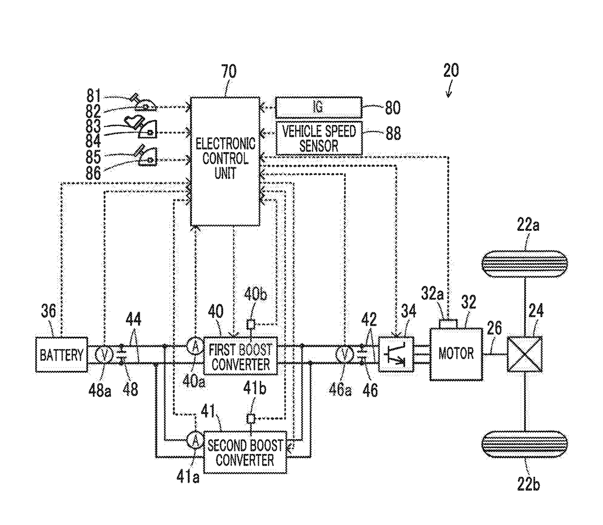
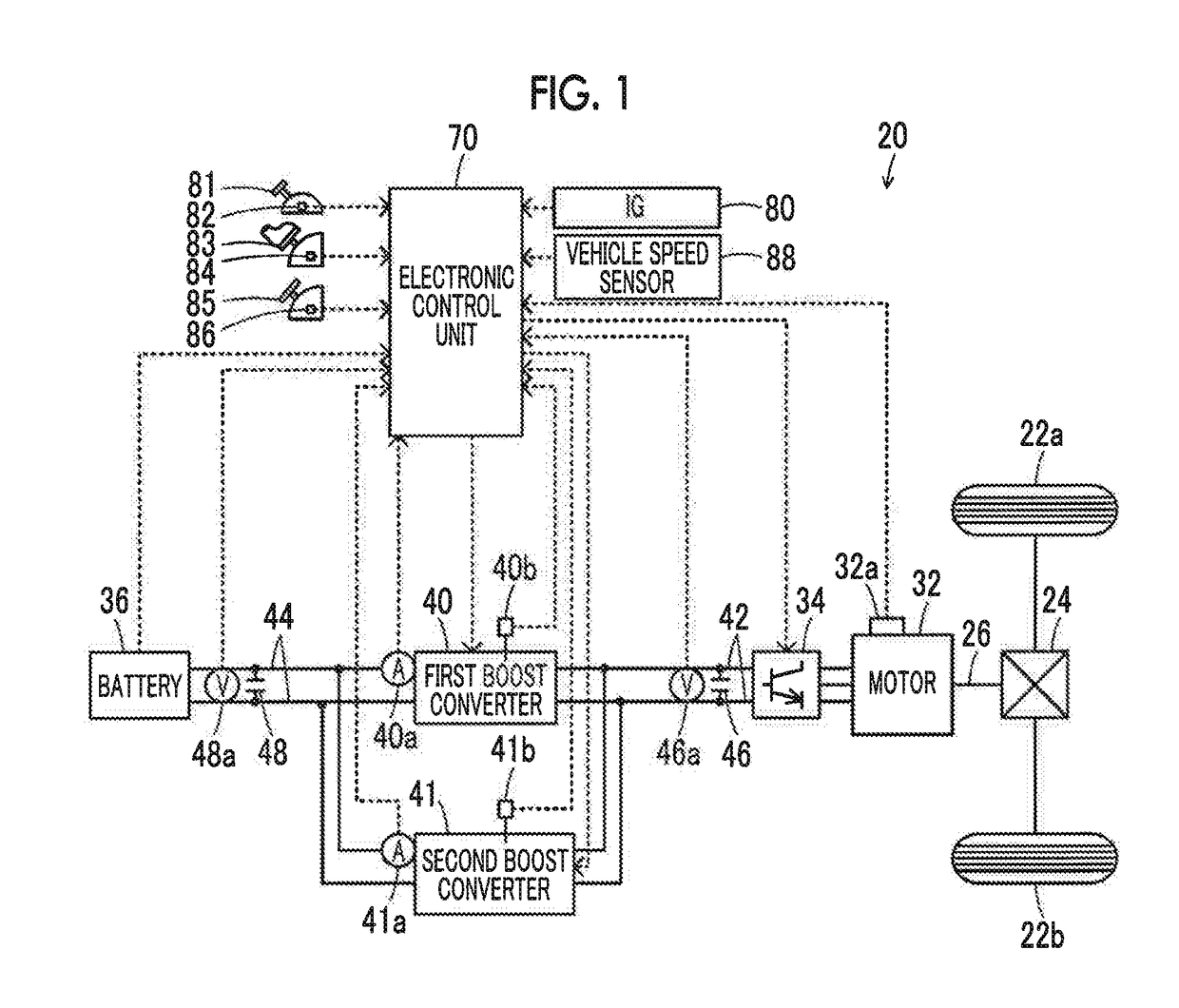
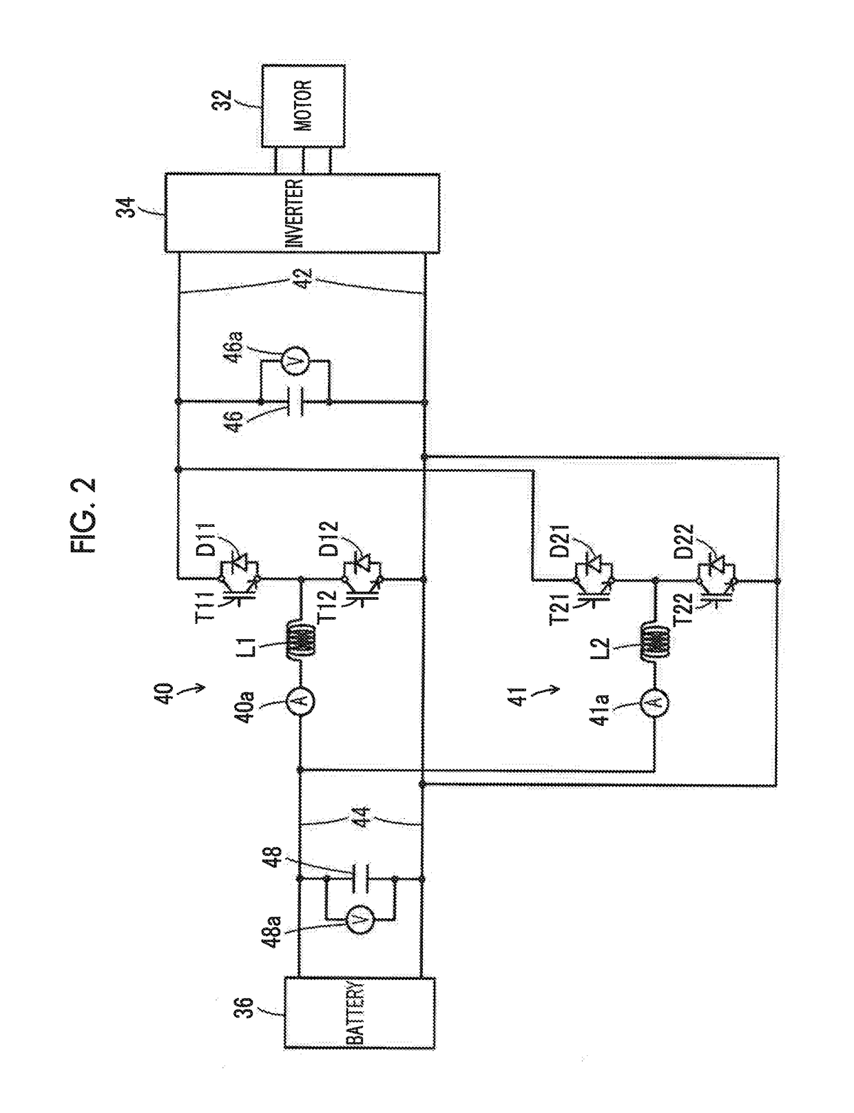
[0024]FIG. 1 is a schematic diagram showing the configuration of an electric vehicle 20 in which a driving device as an embodiment is mounted, and FIG. 2 is a schematic diagram showing the configuration of an electric driving system including a motor 32. As shown in FIG. 1, the electric vehicle 20 of the embodiment includes the motor 32, an inverter 34, a battery 36 as a power storage device, first and second boost converters 40, 41, and an electronic control unit 70. The motor 32, the battery 36, the first and second boost converters 40, 41, and the electronic control unit 70 correspond to a driving device of the embodiment.

[0025]The motor 32 is configured as, for example, a synchronous generator motor, and a rotor thereof is connected to a driving shaft 26 that is connected to driving wheels 22a, 22b through a differential gear 24. The inverter 34 is connected to the motor 32 and also connected to a high voltage side power line 42...


PUM


Abstract

When the heat stress cumulative value of a second boost converter is equal to or greater than a second threshold value that is less than a first threshold value and the heat stress cumulative value of a first boost converter is less than a third threshold value that is equal to or less than the second threshold value, the first boost converter is controlled by voltage control and the second boost converter is controlled by power control. When the heat stress cumulative value of the first boost converter is equal to or greater than the second threshold value and the heat stress cumulative value of the second boost converter is less than the third threshold value, the first boost converter is controlled by the power control and the second boost converter is controlled by the voltage control.

Description

INCORPORATION BY REFERENCE[0001]The disclosure of Japanese Patent Application No. 2016-228854 filed on Nov. 25, 2016 including the specification, drawings and abstract is incorporated herein by reference in its entirety.BACKGROUND1. Field of the Invention[0002]The present disclosure relates to a driving device, and in particular, to a driving device including a motor, a power storage device, and two boost converters.2. Description of Related Art[0003]As this kind of driving device in the related art, a driving device has been proposed which includes a motor, a first power storage device, a first converter for exchanging power with voltage conversion between the first power storage device side and the motor side, a second power storage device, and a second converter for exchanging power with voltage conversion between the second power storage device side and the motor side and which controls the first converter by voltage control to adjust the voltage on the motor side to a target vo...

Claims


Application Information

Patent Timeline
Patent Type & Authority Patents(United States)
IPC IPC(8): H02M3/158B60W10/26B60L11/18B60W20/13B60K6/445B60K6/26
CPCB60L11/1812B60L11/1861B60L11/1868B60W10/26B60W20/13H02M3/1584B60K6/26B60K6/445B60L2210/14B60L3/0023H02M1/32H02M3/158H02P27/06H02M1/327Y02T10/7072Y02T90/14B60L53/22B60L58/20B60K6/46B60W10/06B60W10/08B60W20/00B60W2510/087B60Y2400/61B60Y2300/92Y02T10/62Y02T10/70Y02T10/72H02M1/0022H02M1/0025Y02T90/12
Inventor TAGAWA, YOHSUKE
Owner TOYOTA JIDOSHA KK
Why Eureka
Try Eureka