
Electric handle for implant delivery and delivery system

a technology of implant delivery and electric handle, which is applied in the field of medical instruments, can solve the problems of increasing the incidence of valve degeneration, calcification, mucoid degeneration, etc., and the trauma of surgery is unbearable, so as to avoid operation fatigue during surgery, improve surgical performance, and ensure the effect of reliable positioning and deploying of the prosthetic valv

Active Publication Date: 2018-08-14
SHANGHAI MICROPORT CARDIOFLOW MEDTECH CO LTD
View PDF13 Cites 0 Cited by
  • Summary
  • Abstract
  • Description
  • Claims
  • Application Information

AI Technical Summary

Benefits of technology

[0011]It is therefore an objective of the present invention to provide a control handle and a delivery system for controlled deployment of a prosthetic valve being delivered, which allow the prosthetic valve to be positioned to a target site at a controlled speed in a reliable and accurate manner and can be operated by a physician with a single hand.
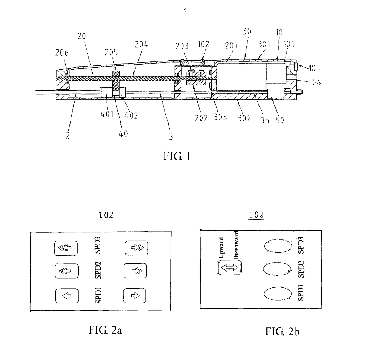
[0020]Enablement of advancement, retraction and selection of different speeds through manipulating the control buttons on the electric handle significantly increases convenience in the physician's operations, results in increased operating convenience and accuracy, and eliminates the need of the physician to exert push or rotating forces during the release process, thereby improving operating stability.
[0021]Therefore, the electric handle consistent with the present invention is capable of operating with high motion accuracy, high motion stability and reliable speed control, ensuring the prosthetic valve to be positioned to a target location in an accurate and reliable manner, and allowing the physician to operate it with a single hand in a simple and convenient way.
[0024]The delivery system according to the present invention allows direction selection and controlled speeds, which enable loading, positioning, deploying and retrieving of the prosthetic valve as well as recovery of the outer tube. All of these operations can be accomplished in a convenient and simple way with consistent quality. Thus, the delivery system achieves high operating accuracy and robustness and can be operated by the physician with a single hand without fatigue.
[0027]2) The button-activated power motor avoids the use of large physical forces in the manual operation and thus avoid operation fatigue during surgery and improve surgical performance.
[0028]3) The physician is allowed to select a proper direction and speed of the delivery system for a specific need in the surgery, which can achieve reliable and accurate positioning and deploying of the prosthetic valve.

Problems solved by technology

In recent years, the aging population has led to an increasing incidence of valve degeneration (including calcification, mucoid degeneration, etc.) and valve damage caused by metabolic disorders in China.
Therefore, traditional heart valve replacement surgery is a highly traumatic operation with obvious accompanied risks and may bring to the patient transient disturbances caused by emboli and other issues associated with the use of the extracorporeal circulation machine, such that a complete recovery typically requires a couple of months.
In addition, for the elders and some special population groups, the trauma of the surgery is unbearable and the recovery needs more time and is sometime even impossible.
However, the manual delivery systems currently used for interventional procedures involves sophisticated operations, imposes demanding requirements on the operating physician and raises a considerable amount of risk in terms of faulty operations.
Additionally, the required operations are laborious and prone to cause hand fatigue of the physician, which is one of the reasons that cause inaccuracy of the operation or misoperations and hence deterioration in surgical performance.
1) It involves sophisticated operations, imposes demanding requirements on the operating physician and raises a considerable amount of risk in terms of faulty operations;
2) The required operations consist of manual rotation and push / pull motions, which are laborious and require the use of both hands. This tends to cause hand fatigue of the physician and thus affects accuracy of the operation and performance of the surgical procedure.
3) It suffers from imprecise catheter motions. Advancement or retraction of the outer tube in the delivery system is enabled by the physician manually pushing, pulling or rotating a proximal handle, which lacks accurate and reliable control of the outer tube's velocity and motion.

Method used


Image

  • Electric handle for implant delivery and delivery system
  • Electric handle for implant delivery and delivery system
  • Electric handle for implant delivery and delivery system

Examples


Embodiment Construction

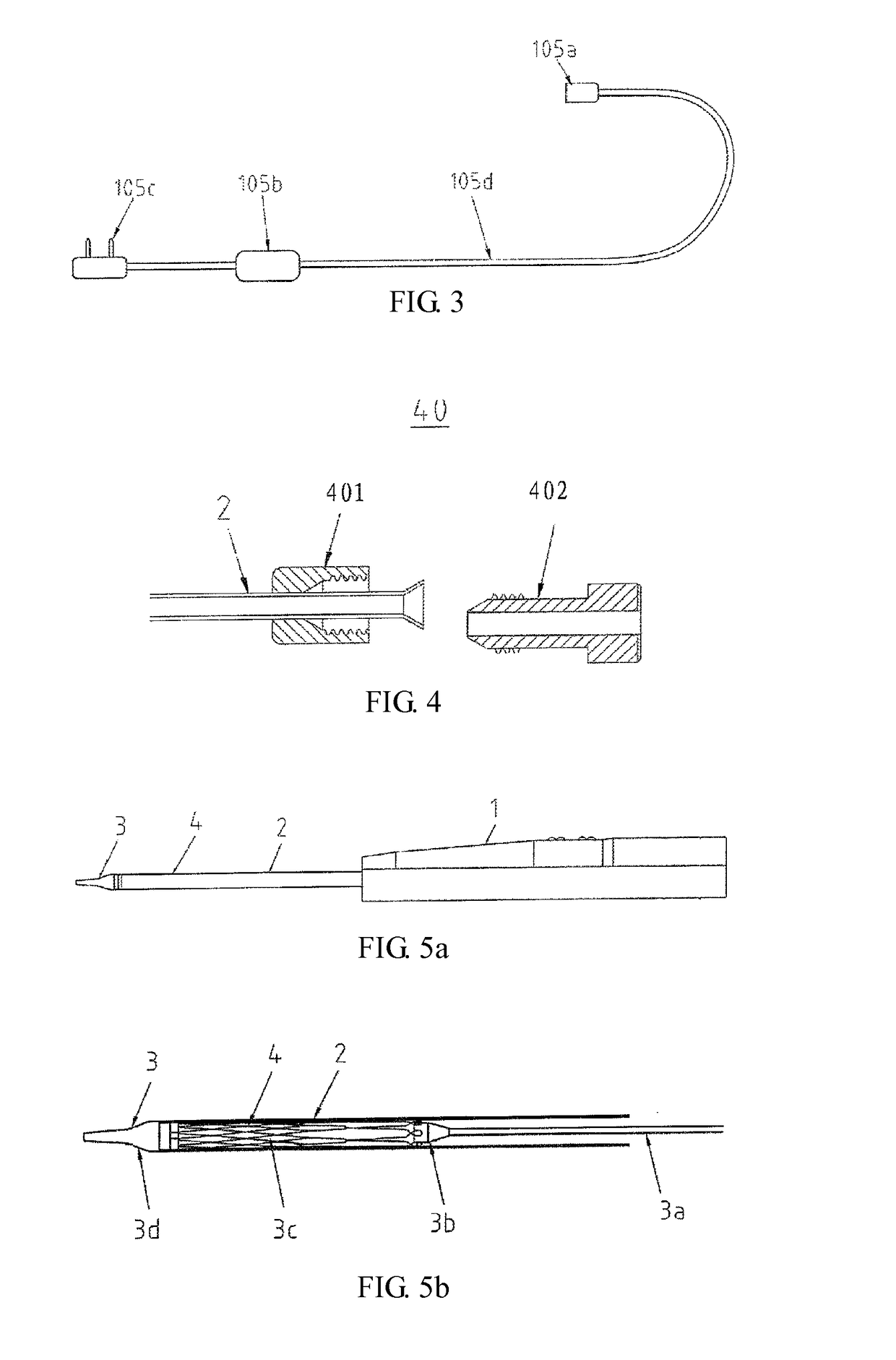
[0037]A few preferred embodiments of the present invention are described below with reference to the drawings which illustrate several examples of electric handles and delivery systems consistent with the present invention. Although the following description is made in the context of the delivery of a prosthetic valve, it is to be understood that the present invention is not limited to this regard as it is also useful in the delivery of other implants such as a blood vessel stent.

[0038]FIG. 1 illustrates an electric handle 1 of the present invention, including an electric control unit 10, a power-driven transmission mechanism 20, a handle housing 30, an outer tube anchor 40 and an inner tube anchor 50.

[0039]As shown in FIG. 1, the control unit 10 is comprised of a controller 101, control buttons 102, a switch 103, a power supply socket 104 and a power supply connector 105.

[0040]The controller 101 serves as a signal conversion unit for receiving an instruction from the control button...


PUM


Abstract

An electric handle for delivering an implant is disclosed. The electric handle (1) includes an electric control unit (10), a power-driven transmission mechanism (20), a handle housing (30), an outer tube anchor (40) and an inner tube anchor (50), wherein: the electric control unit (10) is operatively coupled to the power-driven transmission mechanism (20) to actuate the power-driven transmission mechanism (20); the power-driven transmission mechanism (20) is supported within the handle housing (30) and moveable together with the outer tube anchor (40); the inner tube anchor (50) is disposed within the handle housing (30) and is configured to hold an inner tube (3) of a delivery system; and the outer tube anchor (40) is configured to hold an outer tube (2) of the delivery system and is fixed to an end of the outer tube (2). A delivery system used especially for delivery of prosthetic valves is also disclosed, including an outer tube (2), an inner tube (3), an expandable implant (4) and the electric handle (1).

Description

TECHNICAL FIELD[0001]The present invention relates generally to medical instruments and, in particular, to delivery devices for delivering and placing an implant (e.g., a prosthetic valve or a blood vessel stent). Specifically, in a first aspect, the invention is directed to an electric handle for delivering an implant. In a second aspect, the invention is directed to an implant delivery system incorporating an electric handle.BACKGROUND[0002]Heart valve diseases are some of the most common cardiac diseases in China, and most of them are valve damage caused by rheumatic fever. In recent years, the aging population has led to an increasing incidence of valve degeneration (including calcification, mucoid degeneration, etc.) and valve damage caused by metabolic disorders in China.[0003]Conventionally, heart valve surgery is an open-heart procedure conducted under general anesthesia, during which, following an incision made along the patient's sternum (sternotomy), the heart is stopped ...

Claims


Application Information

Patent Timeline
Patent Type & Authority Patents(United States)
IPC IPC(8): A61F2/24A61F2/966A61F2/95
CPCA61F2/2436A61F2/966A61F2002/9517A61F2/9517
Inventor LIU, XIANGHE, ZHIXIULI, YUGUI, BAOZHUWU, MINGMINGWANG, HAISHANLUO, QIYI
Owner SHANGHAI MICROPORT CARDIOFLOW MEDTECH CO LTD
Learn More