Video capturing system and method for imaging cyclically moving objects

a video capturing and cyclical motion technology, applied in the field of video capturing can solve the problems of inability to practically control, undesirable to have video captured at continuously varying sampling rates, and high impracticality in fixing the operation of the vehicle to match the frequency of cyclically moving objects to the sampling rate of the camera

Active Publication Date: 2018-07-03
EXTOTEC LTD
View PDF23 Cites 3 Cited by
  • Summary
  • Abstract
  • Description
  • Claims
  • Application Information

AI Technical Summary

Benefits of technology

[0017]a light emitter which is aligned with the camera and is operable to emit pulses of light at a controllable emission frequency, such that pulses of light which reach the retro-reflective indicia are reflected backwards towards the camera which is operable to capture a composite image comprising the retro-reflective indicia illuminated by the light emitter and any other matter illuminated by ambient light other than from the light emitter, wherein the light emitter is communicatively coupled to the control module which is configured to control the emission frequency of the light emitter based on the frequency reading, thereby to influence the temporal aliasing of the retro-reflective indicia provided on the cyclically moving object as captured in the video.
[0022]The frequency criteria may dictate that the emission frequency is close to, but not the same as, the sampling frequency. This may create controlled aliasing in the form of a visually observable stroboscopic effect of the cyclically moving object in the video.
[0023]Instead, or in addition, the control module may be operable to receive a user input indicative of a desired operational state, e.g., increase stroboscopic effect, decrease stroboscopic effect, increase emission frequency, decrease emission frequency, etc. The image capturing system may include an input arrangement, e.g., a touchscreen, a slider, or a dial, operable to receive the user input.

Problems solved by technology

However, this is difficult because there are two main factors which influence temporal aliasing, namely i) sampling rate of the camera and ii) frequency of the cyclically moving object, are not practically controllable.
Even if a video camera has an adjustable sampling rate, it might not be possible to adjust it in real-time, or if it is, it may be undesirable to have video captured at continuously varying sampling rates.
Fixing the operation of the vehicle to match the frequency of the cyclically moving object to the sampling rate of the camera is highly impractical.

Method used


Image

  • Video capturing system and method for imaging cyclically moving objects
  • Video capturing system and method for imaging cyclically moving objects
  • Video capturing system and method for imaging cyclically moving objects

Examples


Embodiment Construction

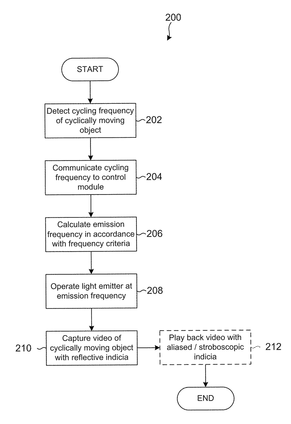
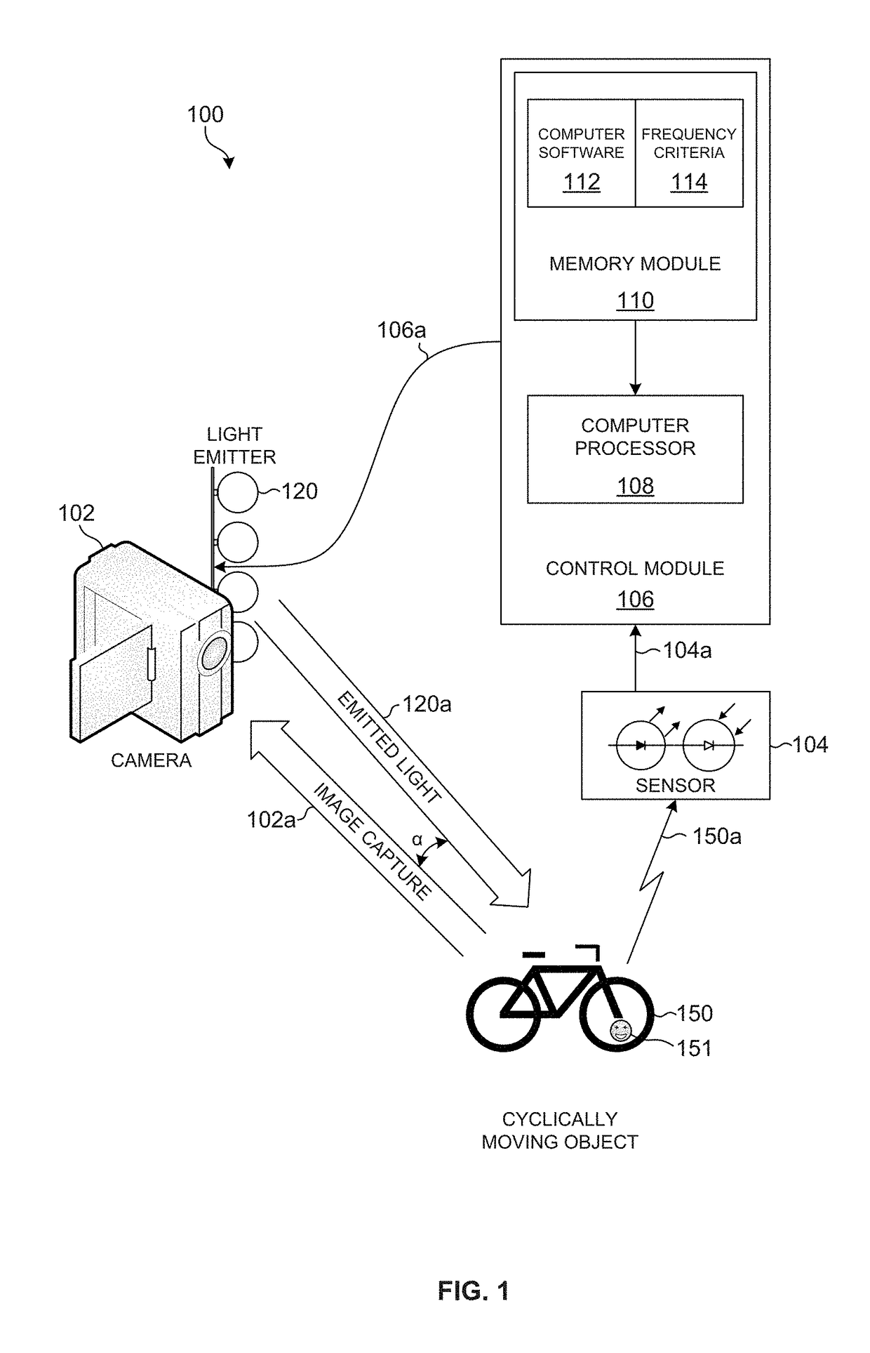
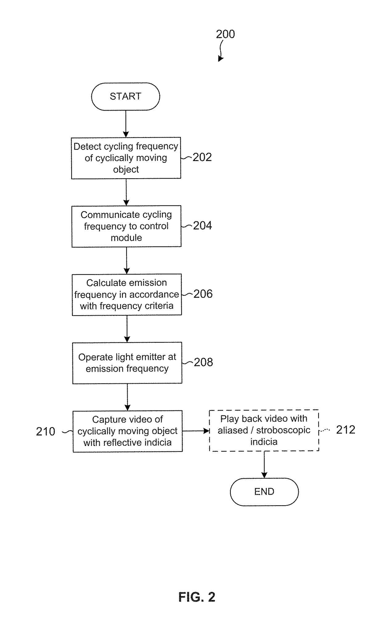
[0052]FIG. 1 shows an example image capturing system 100, in accordance with the invention. The system 100 includes a video camera 102. The video camera 102 may be a conventional or prior art video camera and needs no specific technical modification to operate in accordance with the invention. The video camera 102 is operable, in conventional fashion, to capture a series of images at a defined or definable sampling frequency 102a. The sampling frequency 102a may, for example, be 24 FPS or 50 FPS. The sampling frequency 102a is typically fixed (although may be configurable in some models of video cameras).

[0053]The video camera 102 is directed towards a cyclically moving object 150 which has provided thereon retro-reflective indicia 151. In this example, the cyclically moving object 150 is a bicycle, or more specifically, a bicycle wheel, but it will be understood that the cyclically moving object 150 may be any object which cycles or reciprocates, whether rotationally, linearly, or ...


PUM


Abstract

An image capturing system introduces or controls an aliasing / stroboscopic effect in a cyclically moving object. The system has a camera to capture a series of images to form a video of the cyclically moving object. A sensor detects the cycling frequency of the cyclically moving object and generates a frequency reading with a control module communicably coupled to the sensor. Retro-reflective indicia are provided on the cyclically moving object. A light emitter is aligned with the camera and is operable to emit pulses of light at a controllable emission frequency, such that pulses of light which reach the retro-reflective indicia are reflected backwards towards the camera, wherein the control module is configured to control the emission frequency of the light emitter based on the frequency reading, thereby to influence the temporal aliasing of the retro-reflective indicia provided on the cyclically moving object.

Description

FIELD OF INVENTION[0001]This invention relates broadly to video capture of cyclically moving objects and it relates specifically to an image capturing system and method for imaging cyclically moving objects (e.g., rotating wheels) to achieve a specific or influenced temporal aliasing effect.BACKGROUND OF INVENTION[0002]The Applicant are familiar with the concept of aliasing in signal processing (http: / / en.wikipedia.org / wiki / Aliasing, accessed 18 Feb. 2015). Aliasing in the form of temporal aliasing is practically observable when a video camera operating at a particular sampling rate captures a cyclically moving object and the video of the subject shows the object moving at a false speed. This is colloquially known as the wagon-wheel effect (http: / / en.wikipedia.org / wiki / Wagon-wheel_effect, access 18 February 2015) and more scientifically as the stroboscopic effect (http: / / en.wikipedia.org / wiki / Stroboscopic_effect, accessed 18 Feb. 2015).[0003]It is specifically this temporal aliasing...

Claims


Application Information

Patent Timeline
Patent Type & Authority Patents(United States)
IPC IPC(8): H04N5/262H04N5/225H04N5/235
CPCH04N5/2627H04N5/2354H04N5/2256H04N5/2254H04N5/2621H04N5/2625H04N23/56H04N23/55H04N23/671H04N23/74
Inventor MARCELLIN, PAULMULLHOLLAND, MATTHEW
Owner EXTOTEC LTD
Why Eureka
Try Eureka