Eureka AIR delivers breakthrough ideas for toughest innovation challenges, trusted by R&D personnel around the world.

Laterally diffused metal-oxide-semiconductor field-effect transistor

a metal-oxide-semiconductor and field-effect transistor technology, applied in the field of semiconductor technology, can solve the problems of affecting the reliability of the device and the product, and the on-resistance cannot continue to be reduced, and achieve the effects of high frequency, stable junction capacitance, and guaranteed stability

Active Publication Date: 2018-07-03
CSMC TECH FAB2 CO LTD
View PDF4 Cites 4 Cited by
  • Summary
  • Abstract
  • Description
  • Claims
  • Application Information

AI Technical Summary

Benefits of technology

[0005]Accordingly, it is necessary to provide a laterally diffused metal-oxide-semiconductor field-effect transistor, which can guarantee stability at a very high frequency.
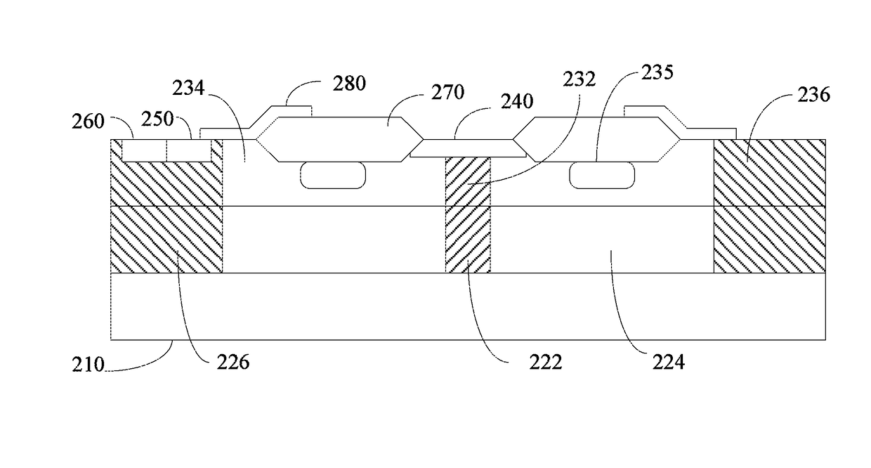
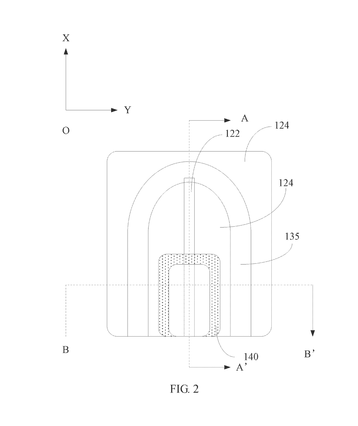
[0006]A laterally diffused metal-oxide-semiconductor field-effect transistor includes a substrate, a source, a drain, a body region, and a well region located on the substrate. The well region includes: an inserting type well, P-type doped, wherein the inserting type well is disposed below the drain and is in contact with the drain and the substrate, a width of the inserting type well is less than a width of the drain; an N well disposed on a periphery of the inserting type well, the N well is in contact with both sides of the drain; and a P well disposed on a periphery of the N well and in contact with the N well. The laterally diffused metal-oxide-semiconductor field-effect transistor further includes a closed P-type field limiting ring, the P-type field limiting ring is disposed in the N well, and is located at a periphery of the drain and below the drain; the inserting type well extends along a longitudinal direction thereof and is in contact with the P-type field limiting ring, the source and the body region are disposed in the P well. In the aforementioned laterally diffused metal-oxide-semiconductor field-effect transistor, the P-type inserting type well extends outwardly over the drain and the N well below the drain, and is connected to the P-type field limiting ring in the drift region, such that the P-type field limiting ring is coupled to the potential of the substrate, thus the P-type field limiting ring is released from the floating state, and it is ensured that a stable junction capacitance can be maintained between the P-type field limiting ring and the N well under the AC high frequency switch state, which can help to improve the dynamic characteristics of the device to avoid the emergence of peak current. In addition, a triple RESURF structure is formed due to the provision of an inserting type well, which helps to increase the doping concentration of the N well and reduce the on-resistance of the device, and helps to improve the breakdown characteristics of the device.

Problems solved by technology

However, the inventor found that in the tens of KHz to hundreds of KHz AC switch applications, the structure of the device may appear peak current, thus affecting the reliability of the device and the product, while the on-resistance cannot continue to be reduced.

Method used


Image

  • Laterally diffused metal-oxide-semiconductor field-effect transistor
  • Laterally diffused metal-oxide-semiconductor field-effect transistor
  • Laterally diffused metal-oxide-semiconductor field-effect transistor

Examples


Embodiment Construction

[0013]Embodiments of the invention are described more fully hereinafter with reference to the accompanying drawings. The various embodiments of the invention may, however, be embodied in many different forms and should not be construed as limited to the embodiments set forth herein. Rather, these embodiments are provided so that this disclosure will be thorough and complete, and will fully convey the scope of the invention to those skilled in the art.

[0014]Unless otherwise defined, all terms (including technical and scientific terms used herein have the same meaning as commonly understood by one of ordinary skill in the art to which this invention belongs. It will be further understood that terms, such as those defined in commonly used dictionaries, should be interpreted as having a meaning that is consistent with their meaning in the context of the relevant art and will not be interpreted in an idealized or overly formal sense unless expressly so defined herein. The term “and / or” a...


PUM


Abstract

Provided is a laterally diffused metal-oxide-semiconductor field-effect transistor, comprising a substrate (110), a source (150), a drain (140), a body region (160), a P-type field-limiting ring (135), and a well region on the substrate (110); the well region comprises an inserted well (122), which has P-type doping and is disposed below the drain and connected to the drain; N wells (124) disposed at the two sides of the inserted well (122); a P well (126) disposed next to the N well (124) and connected to the N well (124); a P-type field-limiting ring (135), which is disposed inside the N well (124), is a closed ring-shaped structure, and is located at the periphery below the drain (140); the inserted well (122) extends in its longitudinal direction to the position where it is in contact with said P-type field-limiting ring (135); the source (150) and the body region (160) are disposed inside the P well (126).

Description

FIELD OF THE INVENTION[0001]The present disclosure relates to semiconductors technology, and more particularly relates to a laterally diffused metal-oxide-semiconductor field-effect transistor having a RESURF structure.BACKGROUND OF THE INVENTION[0002]The basic structure using reduced surface field (RESURF) principle consists of a low-doped P-type substrate and a low-doped N-type epitaxial layer. A P well is formed on the epitaxial layer and N+, P+ are implanted into the P well, such that a transverse P-well / N-epi (P well / N-type epitaxial layer) junction and a longitudinal P-sub / N-epi (P-type substrate / N-type epitaxial layer) junction are formed. Due to a higher doping concentration at both ends of the transverse junction, the breakdown voltage of the transverse junction is lower than that of the longitudinal junction. The basic principle of RESURF is to enable the epitaxial layer to be completely depleted before the transverse junction reaches the critical avalanche breakdown field...

Claims


Application Information

Patent Timeline
Patent Type & Authority Patents(United States)
IPC IPC(8): H01L29/06H01L29/66H01L29/78
CPCH01L29/66681H01L29/7816H01L29/063H01L29/0634H01L29/7869H01L29/42368H01L29/7823H01L29/7835H01L29/0619H01L29/0696
Inventor QI, SHUKUNZHANG, GUANGSHENGSUN, GUIPENGZHANG, SEN
Owner CSMC TECH FAB2 CO LTD
Why Eureka
Eureka Blog
Learn More