
Detection of fault injection attacks

Active Publication Date: 2018-07-03
NUVOTON
View PDF29 Cites 13 Cited by
  • Summary
  • Abstract
  • Description
  • Claims
  • Application Information

AI Technical Summary

Benefits of technology

This approach enables effective detection of fault injection attacks using existing hardware, preventing unauthorized access and information extraction without the need for substantial additional hardware, and can identify various types of attacks during normal IC operation.

Problems solved by technology

A fault injection attack typically involves causing a fault in the circuit, e.g., by physically contacting signal lines, by applying high-power laser or electromagnetic pulses, or by causing glitches on power supply or other external interfaces.
The fault is expected to cause the circuit to output sensitive information, or otherwise assist the attacker in penetrating the circuit or the information it stores.

Method used


Image

  • Detection of fault injection attacks
  • Detection of fault injection attacks
  • Detection of fault injection attacks

Examples


Embodiment Construction

Overview

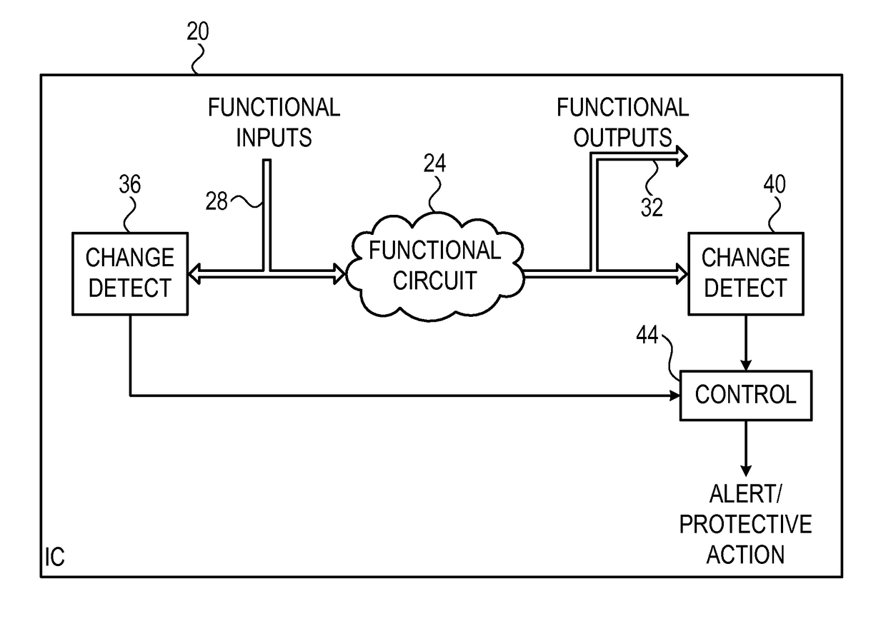
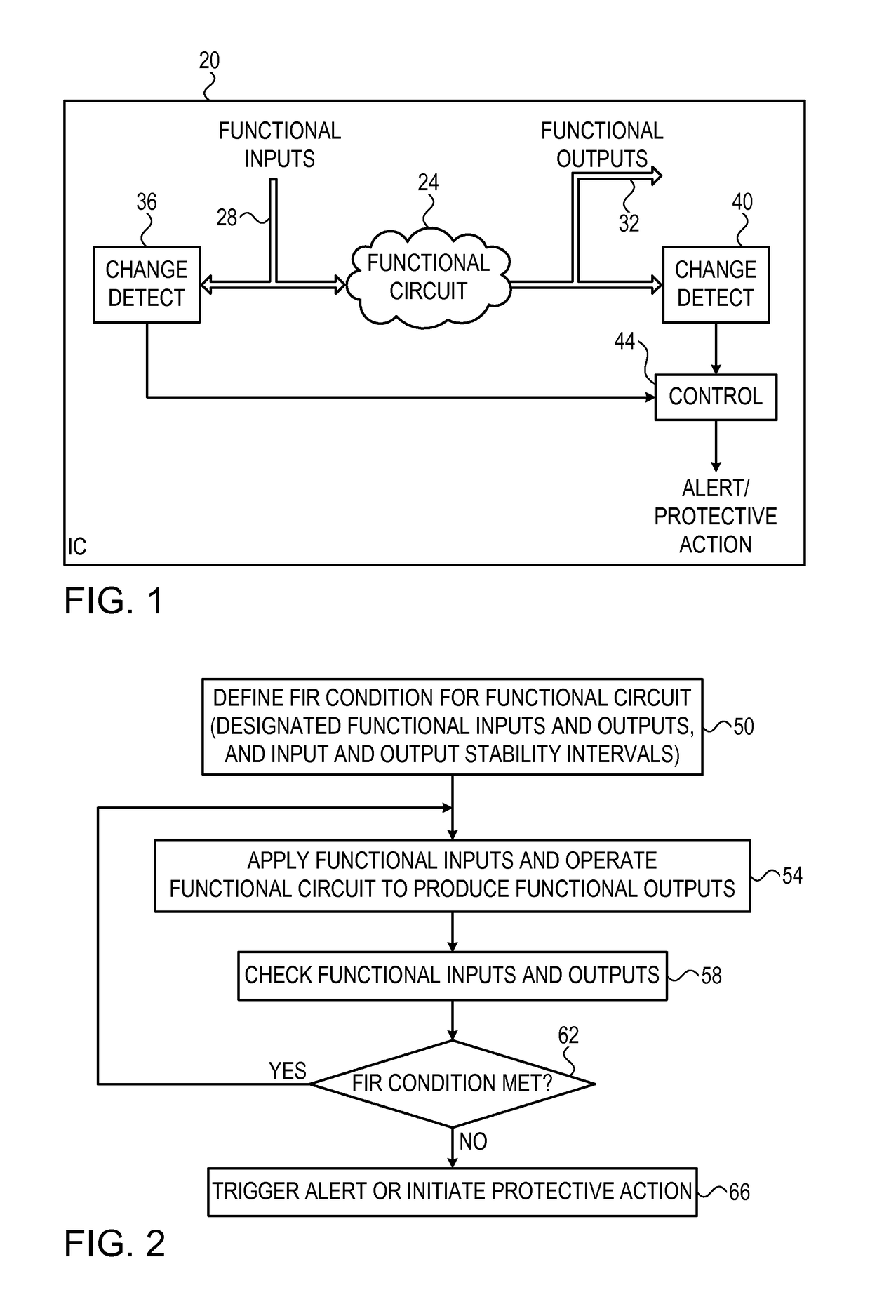
[0019]Embodiments of the present invention that are described herein provide improved methods and systems for detecting and mitigating fault injection attacks on Integrated Circuits (ICs). The disclosed techniques reuse existing functional circuitry of the IC for detecting fault injection attacks.

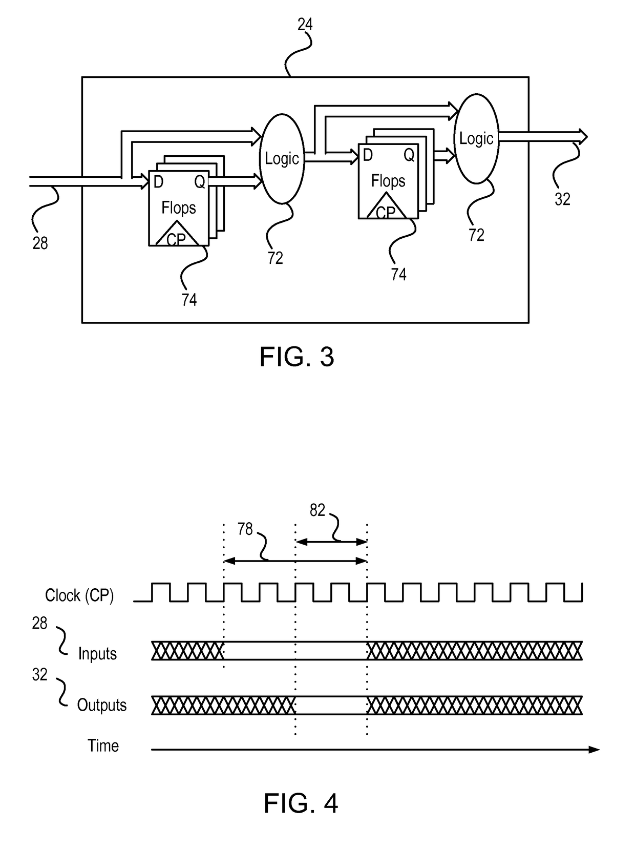
[0020]To qualify for this dual role, the functional circuitry should meet a “Finite Impulse Response” (FIR) condition that is specified with respect to its functional input signals and functional output signals (also referred to herein as functional inputs and functional outputs for brevity). In the present context, the functional circuitry meets the FIR condition if stability of a designated set of (one or more of) the functional inputs during a first time interval guarantees stability of a designated set of (one or more of) the functional outputs during a second time interval that is derived from the first time interval. The term “guaranteed stability” assumes that the circuitry i...


PUM


Abstract

An apparatus for detecting fault injection includes functional circuitry and fault detection circuitry. The functional circuitry is configured to receive one or more functional input signals and to process the functional input signals so as to produce one or more functional output signals. The functional circuitry meets a stability condition that specifies that stability of a designated set of one or more of the functional input signals during a first time interval guarantees stability of a designated set of one or more of the functional output signals during a second time interval that is derived from the first time interval. The fault detection circuitry is configured to monitor the designated functional input and output signals, to evaluate the stability condition based on the monitored functional input and output signals, and to detect a fault injection attempt in response to detecting a deviation from the stability condition.

Description

FIELD OF THE INVENTION[0001]The present invention relates generally to protection of electronic circuitry, and particularly to methods and systems for detecting fault injection attacks.BACKGROUND OF THE INVENTION[0002]Fault injection attacks are a family of techniques used for accessing, analyzing or extracting information from secure electronic circuitry, such as cryptographic circuitry. A fault injection attack typically involves causing a fault in the circuit, e.g., by physically contacting signal lines, by applying high-power laser or electromagnetic pulses, or by causing glitches on power supply or other external interfaces. The fault is expected to cause the circuit to output sensitive information, or otherwise assist the attacker in penetrating the circuit or the information it stores.[0003]Various techniques for detecting and mitigating fault injection attacks are known in the art. For example, U.S. Patent Application Publication 2011 / 0029828, whose disclosure is incorporate...

Claims


Application Information

Patent Timeline
Patent Type & Authority Patents(United States)
IPC IPC(8): G06F21/00G06F21/75
CPCG06F21/75
Inventor HERSHMAN, ZIV
Owner NUVOTON
Learn More