
Working machine

A working machine and function technology, applied in mechanical equipment, motor vehicles, earth movers/shovels, etc., can solve problems such as open circuits that cannot be applied to return fluids and return to the box.

Inactive Publication Date: 2007-07-04
SHIN CATERPILLAR MITSUBISHI LTD CORP
View PDF1 Cites 41 Cited by
  • Summary
  • Abstract
  • Description
  • Claims
  • Application Information

AI Technical Summary

Problems solved by technology

[0007] Also, the described pump / motor and motor / generator combination is limited to a closed circuit and cannot be adapted for use in an open circuit for return fluid exhausted from a fluid pressure actuator back into the tank

Method used


Image

  • Working machine
  • Working machine
  • Working machine

Examples


Embodiment Construction

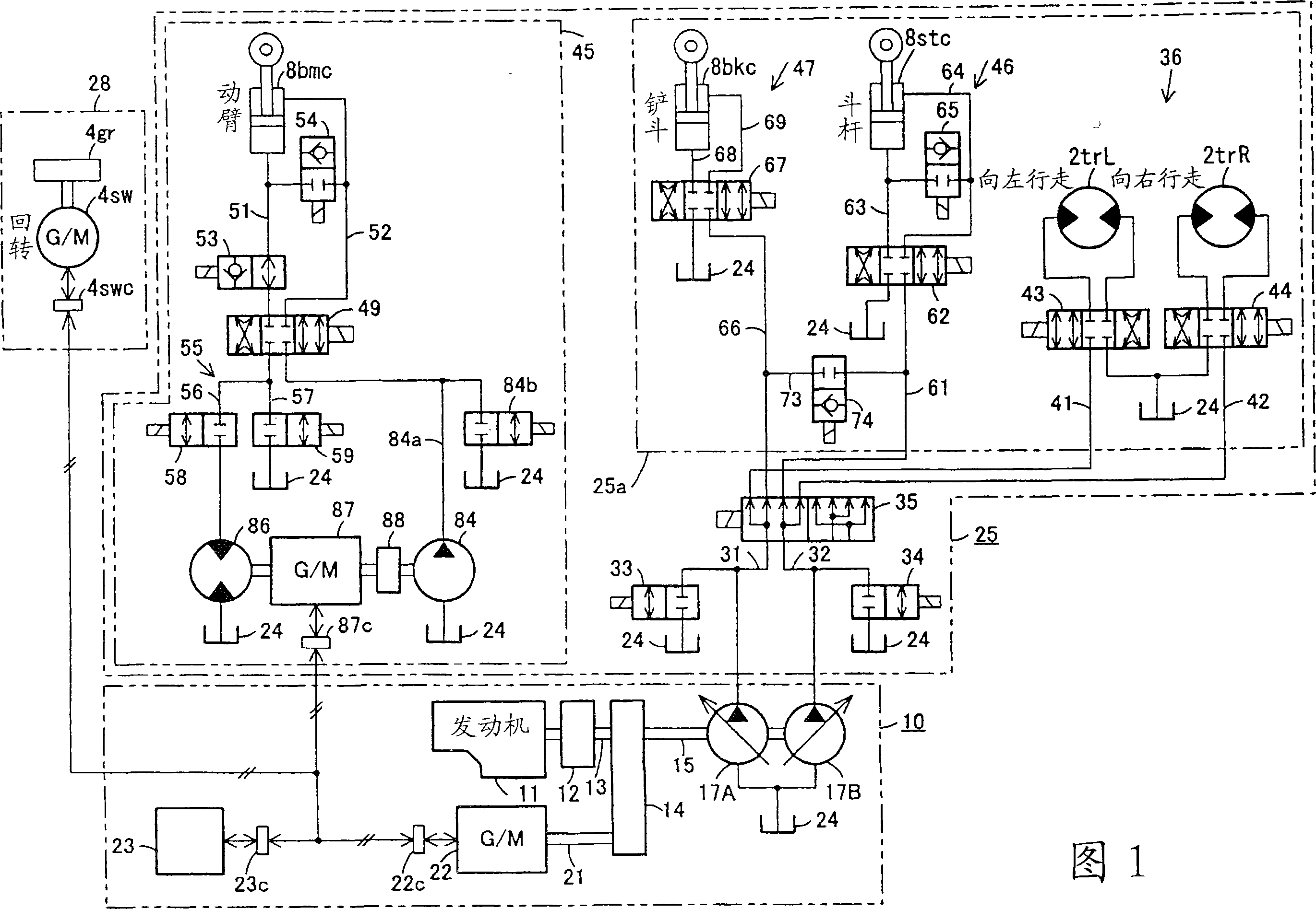
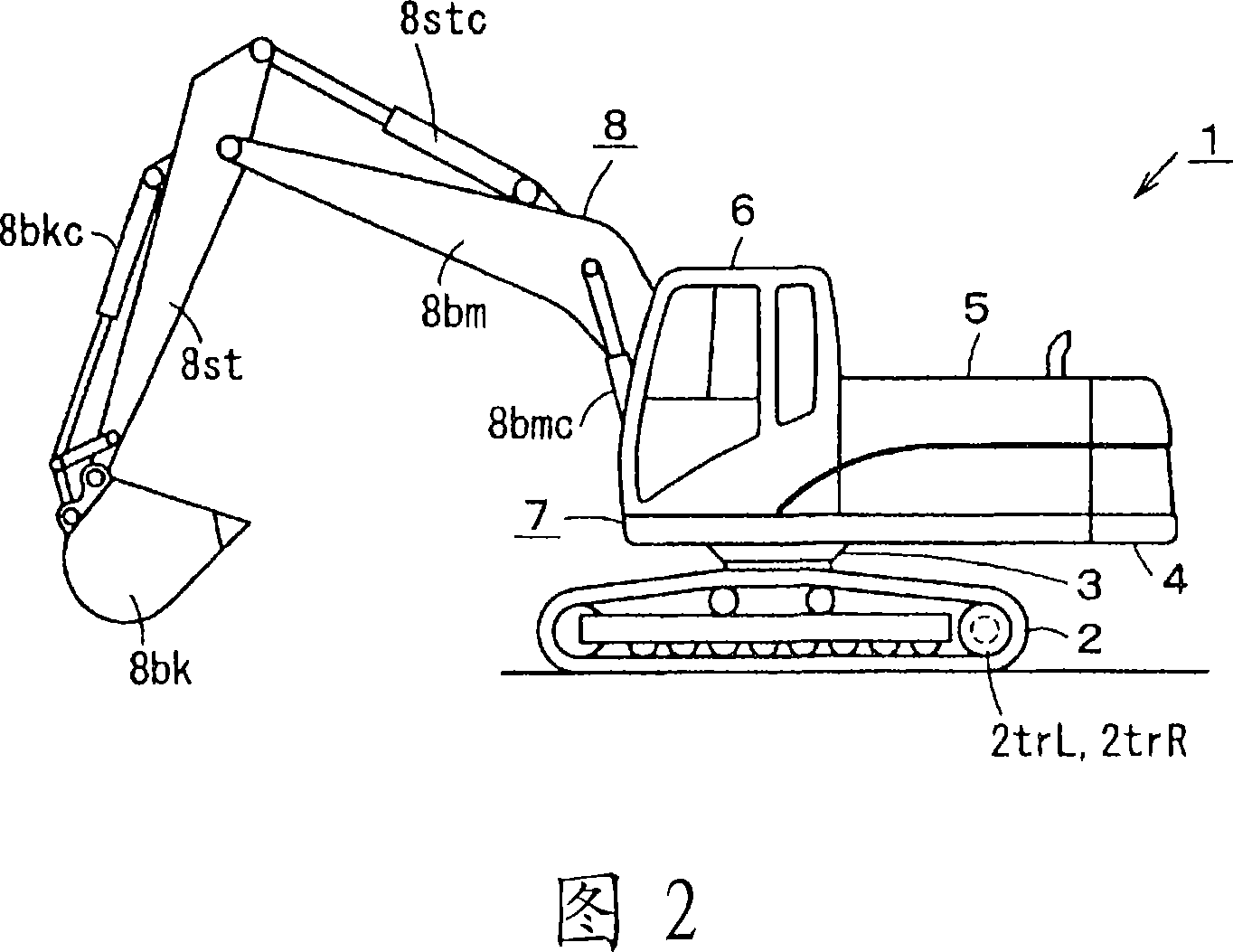
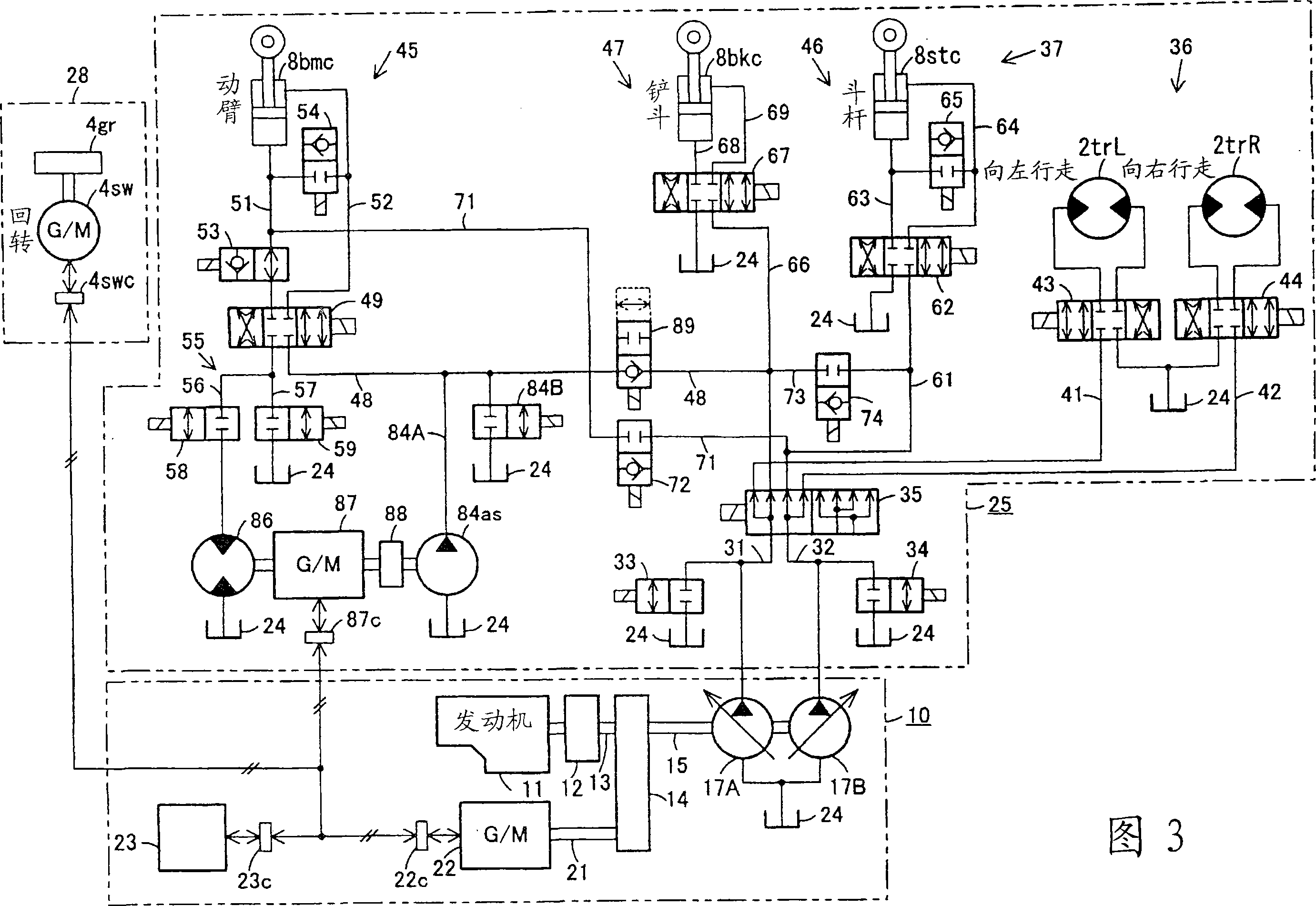
[0028] Hereinafter, the present invention will be specifically described with reference to one embodiment shown in FIGS. 1 and 2 and another embodiment shown in FIG. 3 . In addition, fluid and fluid pressure use working oil and oil pressure.

[0029] First, an embodiment shown in FIG. 1 and FIG. 2 will be described. As shown in FIG. 2 , the working machine 1 is a hydraulic excavator, and an upper slewing bearing 3 is freely rotatable on the lower traveling body 2 . A body 4, on which a power unit 5 such as an engine and a fluid pressure pump, a cab 6 for protecting an operator, and the like are mounted, thereby forming a machine body 7. The lower traveling body 2 has traveling motors 2trL, 2trR driving the left and right crawler belts respectively, and the upper rotating body 4 has a turning motor / generator (not shown in FIG. ).

[0030] A working device 8 is attached to the upper revolving body 4 . The working device 8 is sequentially rotatably connected to a bracket (not ...


PUM


Abstract

A working machine where a boom control circuit (45) for controlling operation fluid to a boom cylinder (8bmc) is provided independently of and separately from a traveling / stick / bucket control circuit (25a) for controlling operation fluid to traveling motors (2trL, 2trR), a stick cylinder (8stc), and a bucket cylinder (8bkc). In the boom control circuit (45), there is a pump (84) for a boom, an energy recovery motor (86) is provided in one return path (56) where return fluid from the boom cylinder (8bmc) flows, a motor / generator (87) for the boom is connected to the energy recovery motor (86), and the pump (84) for the boom is connected to the motor / generator (87) through a clutch (88). Since the boom control circuit (45) is independent, a flow rate required by the boom control circuit (45) can be easily obtained.

Description

technical field [0001] The invention relates to work machines with a hybrid drive. Background technique [0002] A driving device of a working machine such as a hydraulic excavator has a hybrid driving device including a generator driven by an engine, and an accumulator that stores electric power generated by the generator. The pump or the pump / motor is driven by an electric motor or an electric / generator operated by electric power supplied from at least one of these generators and accumulators. [0003] For example, the control circuit for the boom that controls the boom cylinder operates the electric / generator to drive the pump / motor with the power supplied from the generator or accumulator, and the control circuit for the arm that controls the arm cylinder uses the power supplied from the generator Or the electric power supplied by the accumulator makes the motor for the arm work to drive the pump for the arm. In addition, the control circuit for the bucket that controls...

Claims


Application Information

Patent Timeline
IPC IPC(8): E02F9/20F15B21/14E02F9/22B60K6/48B60L50/16B60W10/02B60W10/08B60W10/26B60W20/00
CPCE02F9/2239E02F9/2075E02F9/2217
Inventor 戸泽祥二备中圆古田秀人
Owner SHIN CATERPILLAR MITSUBISHI LTD CORP
Learn More