Heat pipe performance checkout gear

A detection device and heat pipe technology, applied in heat exchange simulation, heat exchange equipment, material thermal development, etc., can solve problems such as heat loss, temperature measurement variation, heat pipe performance variation, unfavorable heat pipes, etc., and achieve good consistency effect with reproducibility, good consistency, avoidance of displacement

Inactive Publication Date: 2007-07-04
FU ZHUN PRECISION IND SHENZHEN +1
View PDF0 Cites 0 Cited by
  • Summary
  • Abstract
  • Description
  • Claims
  • Application Information

AI Technical Summary

Problems solved by technology

[0007] However, the above-mentioned existing heat pipe performance detection device still has the following disadvantages: the lengths of the evaporation section 2a and the condensation section 2b are difficult to accurately control, which are important factors for evaluating the variation of heat pipe performance; Variation due to the influence of the test environment; and the close thermal contact between the heat pipe and the heat source and heat sink are not easy to effectively control and other shortcomings, which are not conducive to accurate evaluation of the performance of the heat pipe. The performance testing device is only suitable for small-scale heat pipe testing on a laboratory scale, and cannot meet the testing requirements required for mass production processes.
[0008] In order to meet the inspection requirements of the mass production process of heat pipes, it is necessary to carry out strict quality control on a large number of heat pipes in various forms; because the detection of mass-produced heat pipes of the same form requires the use of a large number of testing machines at the same time, and these testing machines need Long-term and frequent repeated use; therefore, in addition to the measurement accuracy of the machine itself, it is necessary to strictly control the assembly variation and operation variation of a large number of testing machines; the quality of the testing device will directly affect the quality of production The industry is bound to face the multiple challenges of accuracy, convenience, speed, consistency, reproducibility, and reliability during detection; in view of this, it is necessary to greatly improve the current heat pipe detection device, so that Incorporate the modular design of assembly, operation and component manufacturing to meet the inspection requirements of the mass production process of heat pipes

Method used


Image

  • Heat pipe performance checkout gear
  • Heat pipe performance checkout gear
  • Heat pipe performance checkout gear

Examples


Embodiment Construction

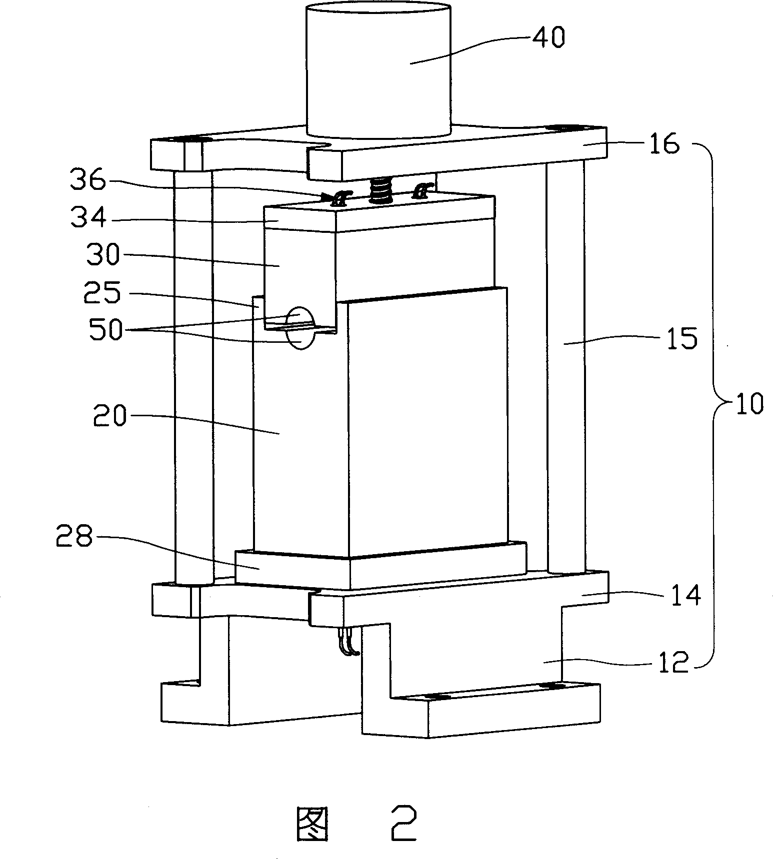
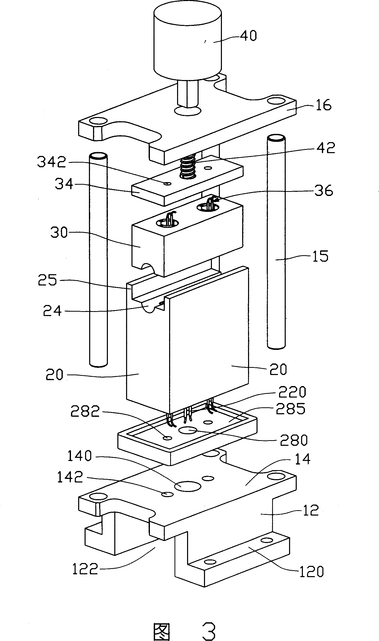
[0022] The heat pipe performance detection device of the present invention will be further described below with reference to FIGS. 2 to 6 .

[0023] Fig. 2 is a perspective view of the appearance of the first embodiment of the heat pipe performance testing device of the present invention, Fig. 3 is a perspective exploded view of Fig. 2, Fig. 4A is a perspective exploded view of the fixing part and the heat insulating bottom plate in Fig. 3, and Fig. 4B is a diagram A three-dimensional view of 4A’s exterior assembly from another angle. The detection device mainly includes a fixed part 20 and a movable part 30 . in:

[0024] The fixed part 20 is a fixed part locked on a stable platform such as a test table or other supporting mechanism, and is made of a material with good thermal conductivity. At least one heating element 22 is pierced inside the fixed part 20, such as an electric heating rod, resistance coil, quartz tube, positive temperature coefficient material (PTC), etc.,...


PUM


Abstract

The invention discloses a detecting device for the performance of heat-pipe that includes a fixed part and a movable part; the heating units are mounted on the fixed part which are used to supply heat, the movable part is on-off connection with the fixed part, at least one measuring accommodating part and at least one positioning mechanism are mounted on the relative surface between the fixed part and the movable part, the heat-pipe contact is mounted on the wall of accommodating part, and at least one temperature sensor are mounted on the wall of accommodating part which contacts closely with the wall of the heat pipe as the index of detecting the performance of heat-pipe.

Description

【Technical field】 [0001] The invention relates to a detection device, in particular to a detection device for detecting the performance of a heat pipe. 【Background technique】 [0002] The basic structure of the heat pipe is that the inner wall of the closed tube is lined with a porous capillary structure layer that is easy to absorb the working fluid, while the central space is in a hollow state, and the total amount of pores equivalent to the capillary structure layer is injected into the vacuumed closed tube. The volume of working fluid can be divided into evaporation section, condensation section and adiabatic section in between according to the relative position of heat absorption and dissipation. [0003] The working principle of the heat pipe is that when the evaporation section absorbs heat, the liquid-phase working fluid contained in the capillary structure layer evaporates, and the vapor pressure increases, and the high-enthalpy vapor flow generated is quickly moved...

Claims


Application Information

Patent Timeline
Patent Type & Authority Applications(China)
IPC IPC(8): G01N25/20G01N25/18
CPCF28D15/0283F28F2200/005
Inventor 刘泰健孙至贤童兆年侯春树
Owner FU ZHUN PRECISION IND SHENZHEN
Why Eureka
Try Eureka