Heat-pipe performance detecting apparatus

A detection device and heat pipe technology, applied in the direction of material thermal development, material thermal conductivity, etc., can solve the problem of heat dissipation and temperature measurement variation, unfavorable heat pipe, heat pipe and heat source and heat sink. problems, achieve good consistency and reproducibility, and avoid shifting

Inactive Publication Date: 2009-12-23
FU ZHUN PRECISION IND SHENZHEN +1
View PDF5 Cites 0 Cited by
  • Summary
  • Abstract
  • Description
  • Claims
  • Application Information

AI Technical Summary

Problems solved by technology

[0007] However, the above-mentioned existing heat pipe performance detection device still has the following disadvantages: the lengths of the evaporation section 2a and the condensation section 2b are difficult to accurately control, which are important factors for evaluating the variation of heat pipe performance; Variation due to the influence of the test environment; and the close thermal contact between the heat pipe and the heat source and heat sink are not easy to effectively control and other shortcomings, which are not conducive to accurate evaluation of the performance of the heat pipe. The performance testing device is only suitable for small-scale heat pipe testing on a laboratory scale, and cannot meet the testing requirements required for mass production processes.
[0008] In order to meet the inspection requirements of the mass production process of heat pipes, it is necessary to strictly control the quality of heat pipes with a large number and various forms; because the inspection of mass-produced heat pipes of the same form requires the use of a large number of testing machines at the same time, and these testing machines Long-term and frequent repeated use is required; therefore, in addition to the measurement accuracy of the machine itself, it is necessary to strictly control the assembly variation and operation variation of a large number of testing machines; the quality of the testing device will directly affect the quality of production Yield and cost, the industry is bound to face the multiple challenges of accuracy, convenience, speed, consistency, reproducibility, and reliability during testing; in view of this, it is necessary to make significant improvements to the current heat pipe testing device, In this way, the fool-proof design of assembly and operation and the modular design of component manufacturing are incorporated together to meet the inspection requirements of the mass production process of heat pipes

Method used


Image

  • Heat-pipe performance detecting apparatus
  • Heat-pipe performance detecting apparatus
  • Heat-pipe performance detecting apparatus

Examples


Embodiment Construction

[0022] The following reference Figure 2 to Figure 6 , The heat pipe performance detection device of the present invention is further explained.

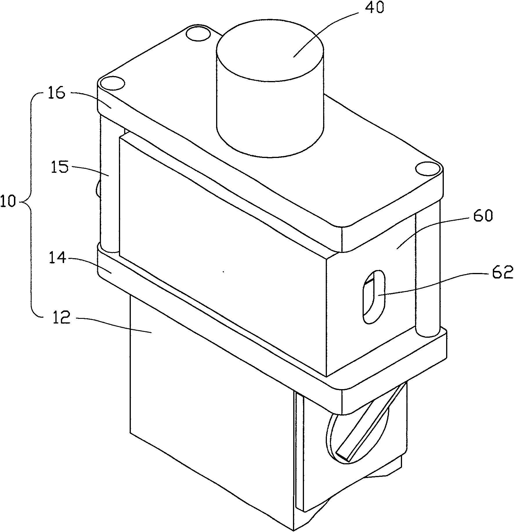
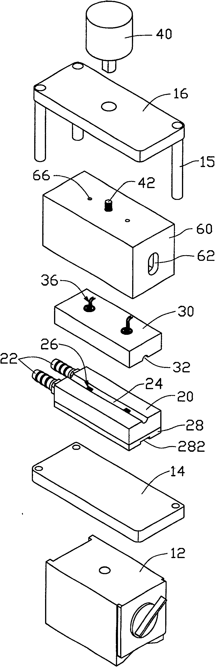
[0023] figure 2 Is an appearance perspective view of the first embodiment of the heat pipe performance detection device of the present invention, image 3 for figure 2 An exploded view of Figure 4 for image 3 A perspective view of the middle cover. The detection device mainly includes a fixed part 20 and a movable part 30. among them:

[0024] The fixed portion 20 is a fixed part that is locked to a stable platform such as a test table or other supporting mechanism, and is made of a material with good thermal conductivity. The fixed portion 20 is provided with a flow channel for the cooling liquid to pass through (not shown in the figure) ), and is connected to an external constant temperature cooling liquid circulation system (not shown) through a cooling liquid inlet and outlet joint 22. The surface of the fixing portion 20 is pro...


PUM


Abstract

The invention discloses a heat pipe performance detection device, which mainly includes a fixed part and a movable part; wherein, the fixed part is provided with a cooling structure for removing the heat transmitted by the heat pipe from a heat source, and the movable part can be separated from the fixed part. Between the fixed part and the movable part, there is at least one measuring accommodating part that can accommodate the heat pipe, and the wall of the measuring accommodating part is in close thermal contact with the heat pipe, and through at least the wall of the measuring accommodating part At least one temperature sensor is arranged on the wall surface of the heat pipe so that it is closely attached to the wall surface of the heat pipe as an indicator for detecting the performance of the heat pipe. The detection device also includes an isolation chamber covering the fixed part and the movable part. The device of the present invention having the above characteristics achieves the construction of a heat pipe performance detection device suitable for mass production process through technical means of fool-proof design and modular design.

Description

【Technical Field】 [0001] The invention relates to a detection device, in particular to a detection device for detecting the performance of a heat pipe. 【Background technique】 [0002] The basic structure of the heat pipe is to line the inner wall of the closed tube with a porous capillary structure layer that easily absorbs working fluid, and the central space is empty, and the evacuated closed tube is filled with a total of pores equivalent to the capillary structure layer. The volume of the working fluid can be divided into the evaporation section, the condensation section and the adiabatic section in between according to the relative position of the absorption and dissipation of heat. [0003] The working principle of the heat pipe is that when the evaporation section absorbs heat, the liquid phase working fluid contained in the capillary structure layer is evaporated, and the vapor pressure is increased, and the generated high enthalpy steam flow is quickly moved along the ce...

Claims


Application Information

Patent Timeline
Patent Type & Authority Patents(China)
IPC IPC(8): G01N25/20G01N25/18
Inventor 刘泰健孙至贤童兆年侯春树
Owner FU ZHUN PRECISION IND SHENZHEN
Why Eureka
Try Eureka