Mgf2 optical thin film containing amorphous silicon oxide binder, optical device having same, and method for producing such mgf2 optical thin film
A technology of optical film and manufacturing method, applied in the field of optical systems, capable of solving problems such as insufficient performance of anti-reflection film
- Summary
- Abstract
- Description
- Claims
- Application Information
AI Technical Summary
Problems solved by technology
Method used
Image

Examples
Embodiment 1-5
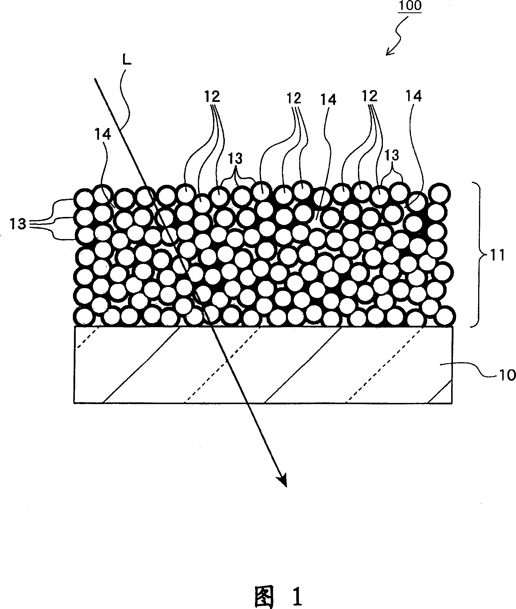
[0192] Take MgF 2 The concentration is 1%, and the hydrofluoric acid / magnesium acetate ratio is 1.95. Mix hydrofluoric acid methanol solution with magnesium acetate methanol solution to prepare MgF 2 Sol solution. Next, the sol solution was subjected to high-temperature and high-pressure treatment at 140° C. for 24 hours. Treated MgF 2 MgF in sol solution 2 The microparticles have an average particle diameter of 20 nm as measured by electron microscope observation. After concentrating the sol solution with a rotary evaporator, it was diluted with 1-propanol to replace 6-7% of the methanol solvent. MgF 2 MgF in sol solution 2 The concentration is 2.5%, and the porous MgF is formed by spin-coating at 2000rpm on a quartz glass substrate with a thickness of 3mm. 2 membrane.
[0193] The substrate was dried at 70° C. for 1 hour, and then returned to room temperature. As the binder solution, the stock solution of Seminstein G-200B, or its dilution with 2-butanol to 1.5 time...
Embodiment 6-8
[0197] Except for MgF 2 The concentration is 1%, the hydrofluoric acid / magnesium acetate ratio is 1.98, 1.99 and 2.0, the hydrofluoric acid methanol solution is mixed into the magnesium acetate methanol solution to prepare MgF 2 Except sol solution, all the other are identical with embodiment 1-5, utilize secondary coating method to form MgF 2 -SiO 2 membrane. Table 1 shows the measurement results of the properties of the obtained film.
Embodiment 1
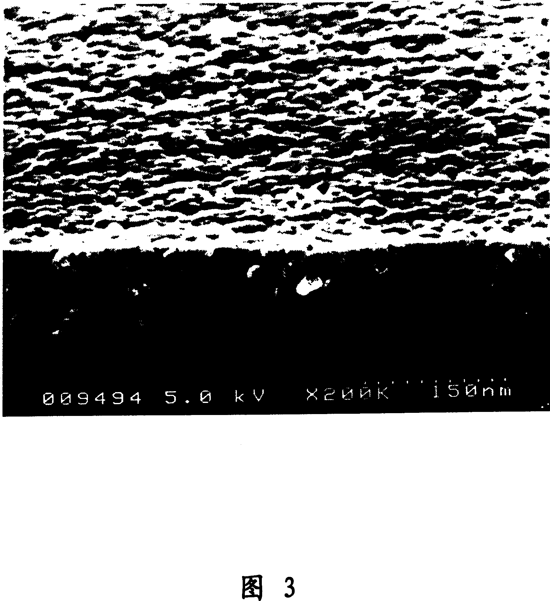
[0200] The MgF that embodiment 1 and 7 obtain 2 -SiO 2 The scanning electron micrographs of the cross-sections of the membranes are shown in Fig. 3 and Fig. 4, respectively. As for the film of Example 1 shown in FIG. 3 , since the edge of the cross section of the film is clear, it can be seen that the film is relatively dense. As shown in FIG. 4 , in the membrane of Example 7, the edge of the membrane cross section was uneven (porous) and unclear.
[0201] MgF is visible on the membrane surface of both 2 Concavities and convexities caused by particles, in MgF 2 SiO is not formed on the film 2 membrane. irradiated to the MgF 2 -SiO 2 The light of the film has a minimum wavelength of 190nm, and the MgF placed on the film surface (outermost) 2 There is no SiO of 5% or more of the wavelength (that is, more than 9.5nm) on the surface of the microparticles. 2 . MgF on the membrane surface 2 SiO on the surface of microparticles 2 For specific thickness, the average thickn...
PUM
| Property | Measurement | Unit |
|---|---|---|
| particle size | aaaaa | aaaaa |
| strength | aaaaa | aaaaa |
| wavelength | aaaaa | aaaaa |
Abstract
Description
Claims
Application Information
 - R&D
- Intellectual Property
- Life Sciences
- Materials
- Tech Scout
- Unparalleled Data Quality
- Higher Quality Content
- 60% Fewer Hallucinations
Browse by: Latest US Patents, China's latest patents, Technical Efficacy Thesaurus, Application Domain, Technology Topic, Popular Technical Reports.
© 2025 PatSnap. All rights reserved.Legal|Privacy policy|Modern Slavery Act Transparency Statement|Sitemap|About US| Contact US: help@patsnap.com