
Method for controlling flow by time-division technology

A flow control, practical technology, applied in the direction of time division multiplexing usage, multi-programming devices, electrical components, etc., can solve problems such as CPU processing overload, system stability impact, large data volume, etc., to achieve flow control and eliminate hidden dangers , to reduce the effect of impact

Inactive Publication Date: 2007-06-20
ZTE CORP
View PDF0 Cites 5 Cited by
  • Summary
  • Abstract
  • Description
  • Claims
  • Application Information

AI Technical Summary

Problems solved by technology

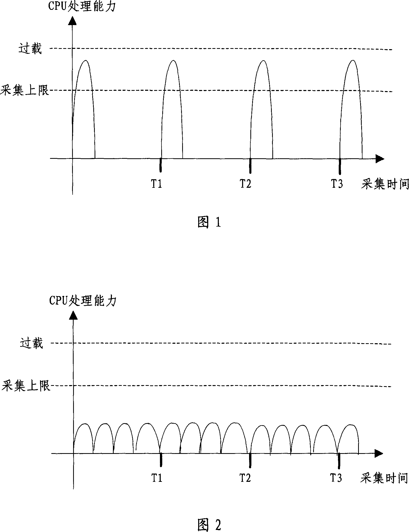
The usual data collection method is to reach the collection time point, the system reports the collected data to the data collector at one time, or the data collector sends the collection command at one time when the time point is reached, so that if the amount of data collected by the system is relatively large , the CPU occupancy rate of the system will show periodic peaks, as shown in Figure 1, and the peaks are narrow, that is, in a cycle, it only takes up a short period of time, but in this short period of time, the CPU processing The amount is very large, and from the perspective of the entire time period, the CPU has not been fully utilized, and has caused a great impact on the stability of the system
[0003] A lot of data needs to be collected in the CDMA system. Under the limited CPU processing capacity, in order to maintain the stability of the system, the flow control of the system must be effectively realized to avoid the CPU processing overload caused by the large amount of data in the system.
If the above flow control problems cannot be effectively handled, there will be great hidden dangers in the stability of the system.

Method used


Image

  • Method for controlling flow by time-division technology
  • Method for controlling flow by time-division technology

Examples


Embodiment Construction

[0027] Various preferred embodiments of the present invention will be described in detail below in conjunction with the accompanying drawings.

[0028] In the method utilizing time-division technology of the present invention to realize flow control, the flow control process in the CDMA system is described as follows:

[0029] The CDMA data collection equipment of the method of the present invention is composed of two parts: a data collector and a system device, where the data collector is an operation and maintenance system in CDMA, and the system device is a communication network element. According to different collection methods, flow control can be controlled by data collectors or system devices, and the realization principles are the same. Control method of the present invention comprises following two modes:

[0030] Method 1: Control by system equipment.

[0031] The basic process is: the data collector establishes the collection task and sets the data collection peri...


PUM


Abstract

The invention discloses a flow control method using time-division technology, comprising the following steps: calculate CPU collection and handling capacity in the system according to the system CPU handling capacity and upper limit of CPU data collection occupancy rate; according to the system period to collect maximum data size, the minimum data size is calculated that system period collected maximum data size divide the system CPU collection and handling capacity, the actual system collecting period is no less than minimum data size; calculate the number of the minimum time slice according to the actual system collecting period and the actual collected data size, and handling capacity of each time slice is not more than CPU collection and handling capabilities; start the collecting timer according to the actual system collecting cycle by the times not less than the minimum number of time slice. The method of the invention fully uses the CPU resources, reduce the impact of system stability, and effectively achieve the purpose of flow control by dividing the data processing into a number of sub-sections in one periodic time.

Description

technical field [0001] The invention relates to a flow control method, in particular to a method for realizing flow control by using time-division technology. Background technique [0002] In mobile communication systems such as CDMA, it is necessary to collect various types of system data for debugging, analysis, and reporting. Several important characteristics of this type of data collection are: large amount of data, periodicity, and low real-time requirements. The usual data collection method is to reach the collection time point, the system reports the collected data to the data collector at one time, or the data collector sends the collection command at one time when the time point is reached, so that if the amount of data collected by the system is relatively large , the CPU occupancy rate of the system will show periodic peaks, as shown in Figure 1, and the peaks are narrow, that is, in a cycle, it only takes up a short period of time, but in this short period of ti...

Claims


Application Information

Patent Timeline
IPC IPC(8): H04L29/02H04L5/22G06F9/46
Inventor 谢建光尧幸
Owner ZTE CORP
Learn More