
Magnetron sputtering coating equipment and preparation method of ITO glass

A technology of magnetron sputtering coating and equipment, applied in the field of sputtering coating, which can solve the problems of lack of adjustable sputtering channel size, inability to adjust the inclination angle of the target, and reduced product yield, so as to improve product quality and scope of application The effect of wide and high utilization rate

Active Publication Date: 2021-01-22
凯盛信息显示材料(黄山)有限公司
View PDF6 Cites 0 Cited by
  • Summary
  • Abstract
  • Description
  • Claims
  • Application Information

AI Technical Summary

Problems solved by technology

[0003] However, there are still obvious defects in its use: 1. The magnetron target in the above-mentioned device moves around the workpiece, but the target itself cannot rotate, resulting in only the target opposite to the workpiece being able to rotate. 2. The inclination angle of the target in the above device cannot be adjusted, and the gradient sputtering coating cannot be realized by adjusting the distance difference, so its use effect is very limited; 3. The above-mentioned device lacks a shielding cover with adjustable sputtering channel size, and the scattered target particles will be plated to the part of the workpiece that does not need to be coated under the action of the electric field, which reduces the yield of the product; 4. The above-mentioned equipment is processing glass During the coating process, sputters will accumulate and the sputtering channel will be blocked, and manual processing after shutdown is required, which is inconvenient to use

Method used


Image

  • Magnetron sputtering coating equipment and preparation method of ITO glass
  • Magnetron sputtering coating equipment and preparation method of ITO glass
  • Magnetron sputtering coating equipment and preparation method of ITO glass

Examples


Embodiment Construction

[0034] The following will clearly and completely describe the technical solutions in the embodiments of the present invention with reference to the accompanying drawings in the embodiments of the present invention. Obviously, the described embodiments are only some, not all, embodiments of the present invention. Based on the embodiments of the present invention, all other embodiments obtained by persons of ordinary skill in the art without making creative efforts belong to the protection scope of the present invention.

[0035] see Figure 1-6 , the present invention provides a technical solution:

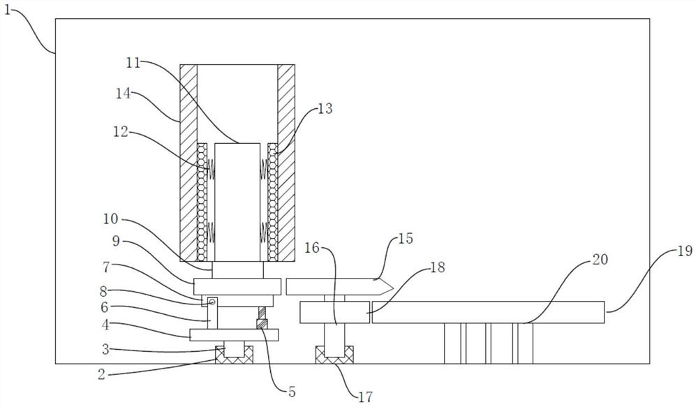
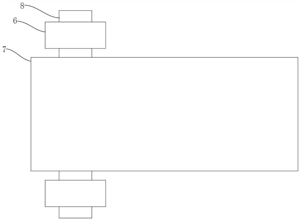
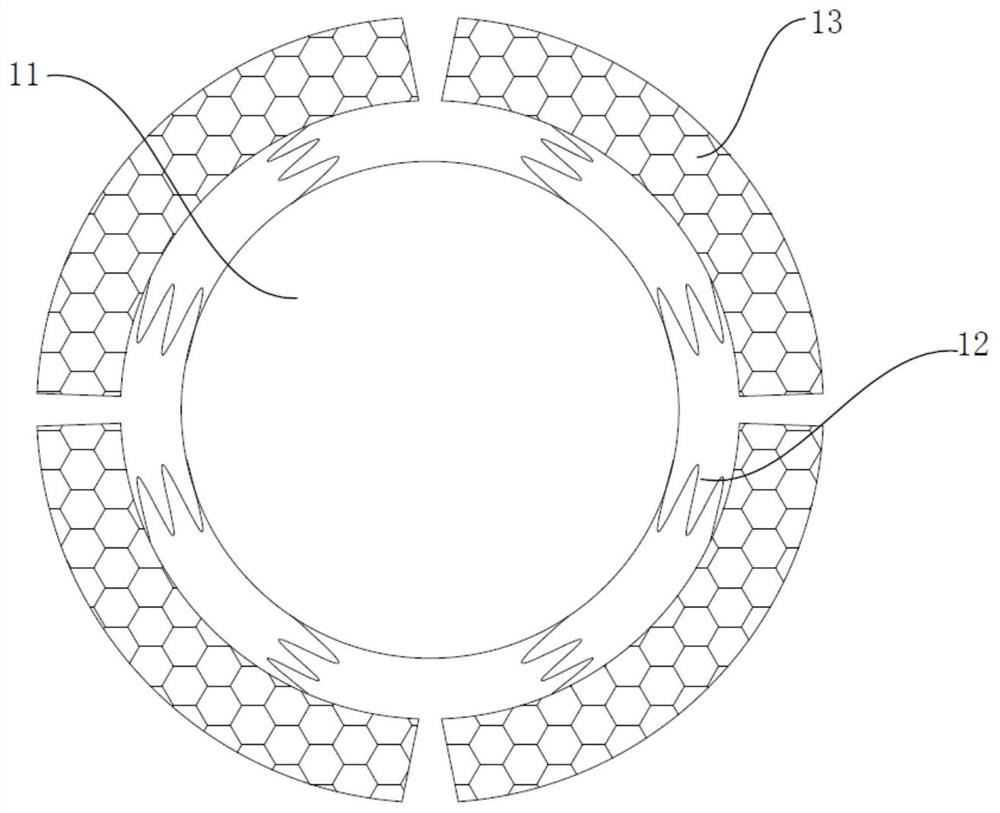
[0036] A magnetron sputtering coating equipment, comprising a coating chamber 1, a bearing seat-2 is fixedly arranged in the coating chamber 1, a transmission shaft-3 is hingedly arranged in the bearing seat-2, the transmission shaft-3 is rotatable, and the transmission shaft-3 A base plate 4 is fixedly installed on the base plate 4, and a hydraulic cylinder 5 and two support rods...


PUM


Abstract

The invention discloses magnetron sputtering coating equipment and a preparation method of ITO glass. The magnetron sputtering coating equipment comprises a coating chamber, a hydraulic cylinder and two supporting rods are fixedly arranged on a base plate, and an arc-shaped adsorption pad is arranged in a cylindrical magnetron target in a sleeved manner. A single-tooth gear is arranged on the sideface of a complete gear in an engaged manner. A solid partition plate and a hollow partition plate are fixedly arranged on a gear disc, sliding rods are symmetrically and movably arranged in the hollow partition plate, cleaning brushes are fixedly arranged on the sides, away from the circle center of the gear disc, of the sliding rods, a push rod is fixed to an arc-shaped electromagnetic plate, and an electromagnetic rod is arranged in the center of the hollow partition plate. According to the magnetron sputtering coating equipment, the target can intermittently rotate by a certain angle along with the rotation of a workpiece, the inclination angle of the target can also be adjusted, various coating requirements are met, the distance between shielding covers is adjustable, and a sputtering channel can be cleaned while sputtering coating is carried out. The preparation method of the ITO glass of the magnetron sputtering coating equipment is further provided, and the preparation methodis very worthy of popularization.

Description

technical field [0001] The invention relates to the technical field of sputtering coating, in particular to a magnetron sputtering coating equipment and a preparation method of ITO glass. Background technique [0002] In the prior art, a magnetron sputtering coating equipment with the application number "201910352464.1" includes a vacuum chamber, the inner lower end of the vacuum chamber is provided with a substrate platform, the upper end of the substrate platform is provided with a target holder, and the upper end of the target holder is There is a fixing device, the upper end of the vacuum chamber is provided with a rotating device, the lower end of the rotating device is provided with a connecting piece, and one end of the connecting piece is provided with a magnetron target. The inner upper end is connected, two sets of fixed rods are set between the upper ends of the fixed frame, the fixed rods are covered with a slide plate, and two sets of movable rods are interspers...

Claims


Application Information

Patent Timeline
IPC IPC(8): C23C14/35C23C14/50C23C14/54C23C14/56C03C17/00
CPCC23C14/35C23C14/505C23C14/54C23C14/564C03C17/001
Inventor 朱汪根张见平许波胡松吴俊保冯治国
Owner 凯盛信息显示材料(黄山)有限公司
Learn More