
Filling of pressure vessels with cryogenically solidified gas

A low-temperature liquefied gas, pressure vessel technology, applied in pressure vessels, non-pressure vessels, equipment installed in pressure vessels, etc., can solve the high operation and maintenance costs, high investment costs, piston or diaphragm compressors. pressure and other problems, to achieve the effect of good measurement performance

Inactive Publication Date: 2007-06-13
LAIR LIQUIDE SA POUR LETUDE & LEXPLOITATION DES PROCEDES GEORGES CLAUDE
View PDF4 Cites 7 Cited by
  • Summary
  • Abstract
  • Description
  • Claims
  • Application Information

AI Technical Summary

Problems solved by technology

[0004] Requires very expensive and complex piston or diaphragm compressors to generate very high pressures
This entails high investment costs and high operating and maintenance costs
Furthermore, a correspondingly complex and expensive downstream gas supply is required for these pressures

Method used


Image

  • Filling of pressure vessels with cryogenically solidified gas
  • Filling of pressure vessels with cryogenically solidified gas

Examples


Embodiment Construction

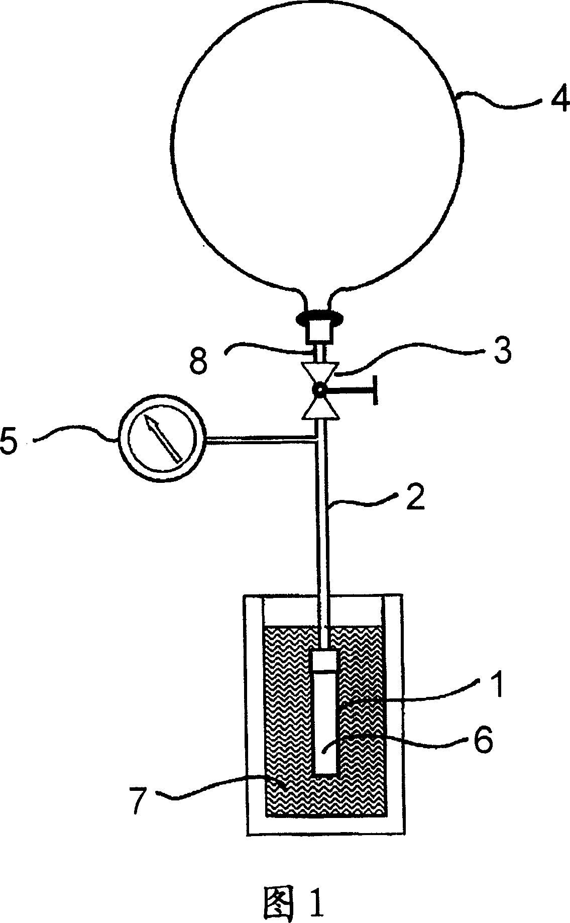
[0039] Figure 1 shows a pressure vessel 1, a filling tube 2 with a pipe connection 8, a shut-off valve 3, a gas cylinder 4 filled with argon (1 bar, 15 °C), a pressure gauge 5, argon ice in the pressure vessel 1 6 and a pool with liquid nitrogen 7 .

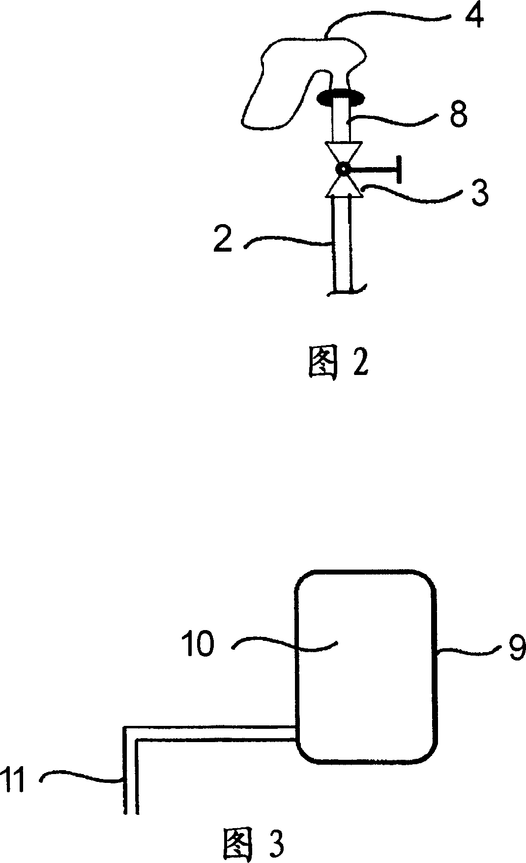
[0040] To determine the increase in density, a defined mass of argon from cylinder 4 is frozen to a precalculated container volume. To this end, a gas cylinder 4 is connected via a thin-walled tube 2 to a container 1 immersed in liquid nitrogen 7 . Once the air cylinder 4 has been emptied ( FIG. 2 ; showing in detail the emptied cylinder of the apparatus of FIG. 1 ), the shut-off valve 3 is closed and the container 1 can be removed from the liquid nitrogen bath. The pressure increase in the test vessel 1 due to the warming of the cold argon can be monitored using a pressure gauge 5 . The final pressure corresponding to the filling mass is reached after complete warming to ambient pressure.

[0041] FIG. 2 shows the situation w...


PUM


Abstract

In the method for filling a pressure vessel (1), in particular a pressure vessel in airbag systems, with a gas or gas mixture, one or more cryogenically solidified gases and optionally a cryogenically liquefied gas are introduced into a pressure vessel (1).

Description

technical field [0001] The invention relates to a method for filling a pressure vessel, in particular a pressure vessel of an airbag system, with gas. Background technique [0002] Airbags in vehicles are increasingly using new types of gas generators that inflate the airbag within milliseconds in the event of an accident. A high pressure gas storage system is used as the gas generator. [0003] Gas generators filled with various gases pose enormous technical problems in production both in their production and filling with pressures of up to 1000 bar. Especially the heat of compression during fast filling means that (so high) pressures are required in order to introduce an exactly predetermined mass of gas. These are critical to the subsequent inflation characteristics of the airbag. [0004] Very expensive and complex piston or diaphragm compressors are required to generate very high pressures. This requires high investment costs and high operating and maintenance costs...

Claims


Application Information

Patent Timeline
Patent Type & Authority Applications(China)
IPC IPC(8): F17C5/02F17C5/06F17C7/04F17C9/02
CPCF17C7/04F17C2221/03F17C2225/0161F17C2270/0181F17C5/06F17C2223/035F17C2250/043F17C9/02F17C2223/0138F17C5/02F17C2201/0128F17C2221/016F17C2227/0337F17C2225/0176F17C2227/0341F17C2225/033F17C2201/058F17C2223/0123F17C2201/0104F17C2205/0323
Inventor U·克勒贝F·米歇尔A·德谢纳
Owner LAIR LIQUIDE SA POUR LETUDE & LEXPLOITATION DES PROCEDES GEORGES CLAUDE
Learn More