Hinge device and electronic equipment using the same

A technology of hinge device and booster device, which is applied in branch office equipment, telephone communication, electrical components, etc. It can solve the problems of torque variation and the inability of the rotating disc to rotate smoothly, so as to achieve stable opening and closing torque and stable maintenance Fixed rotating part, good operability effect

Inactive Publication Date: 2007-05-23
OHASHI TECHNICA
View PDF3 Cites 0 Cited by
  • Summary
  • Abstract
  • Description
  • Claims
  • Application Information

AI Technical Summary

Problems solved by technology

[0010] However, in the hinge device described in Patent Document 2, although the first and second balls are always separated from each other by substantially the same length from the rotational axis of the movable disk, the first and second balls The distance from the rotation axis moves in the direction of expansion or contraction in the same way, so there is a problem that the torque changes with the rotation angle
In addition, in the hinge device described in Patent Document 3, since the large-radius position and the small-radius position that support the rotating disk portion are located at one side with respect to the rotation axis, it cannot be performed smoothly with the rotating disk portion. turning problem

Method used


Image

  • Hinge device and electronic equipment using the same
  • Hinge device and electronic equipment using the same
  • Hinge device and electronic equipment using the same

Examples


Embodiment Construction

[0035] The following explains the implementation of the invention according to the attached figure.

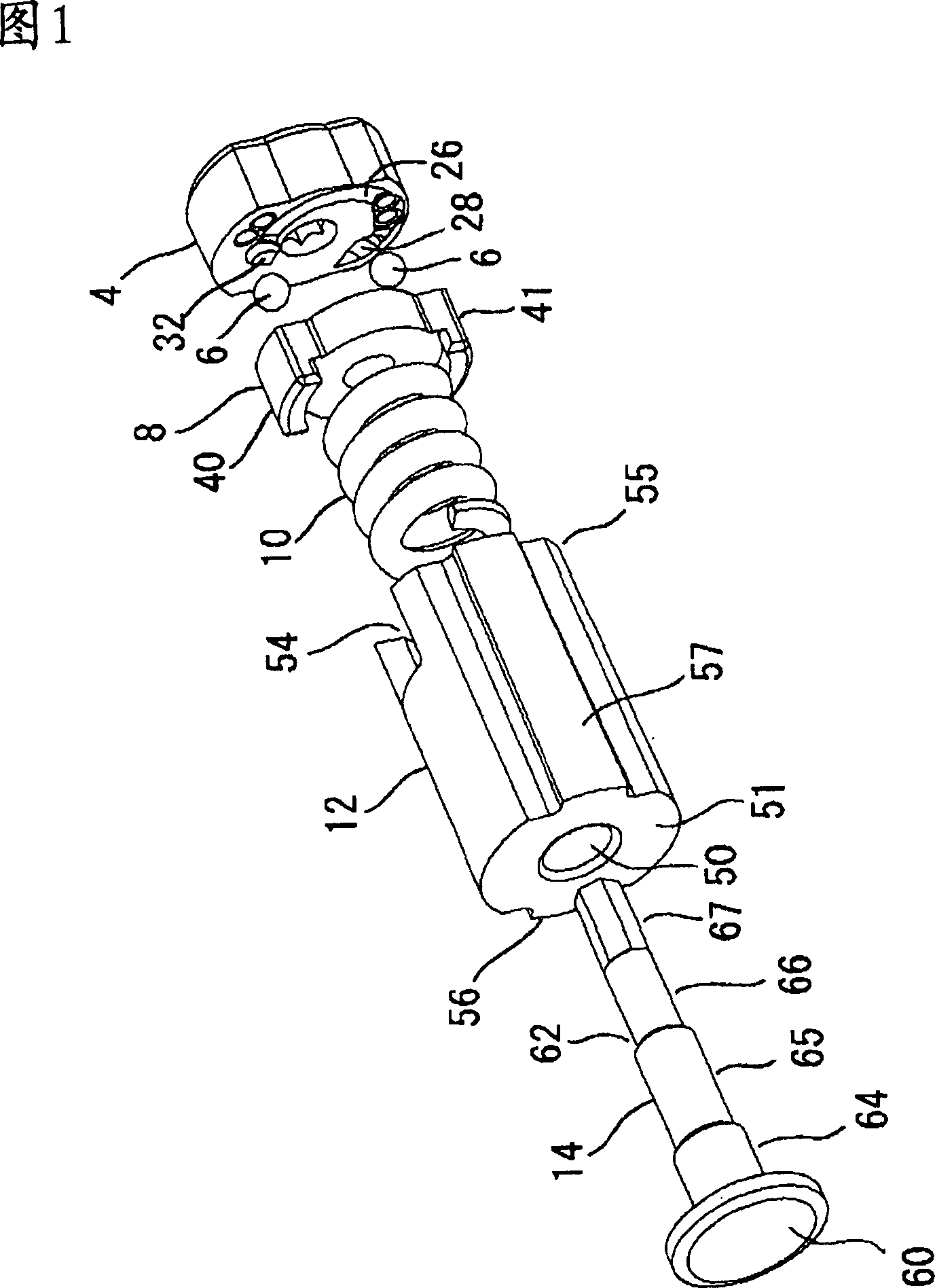
[0036] Figure 1 is the first embodiment, which indicates that the hinge device 2 is used for the decomposition stereo diagram of the hinge device 2 on the electronic device such as folding game consoles or mobile phones. The components of this hinge device 2 include plates 4. Two spheres 6, card components 8, spiral spring 10, cylindrical components 12, and shaft body 14. In these components, the cam is composed of disk 4, sphere 6, and card component 8. In addition, the surface shape of the hinge device 2 consists of plate 4, cylindrical component 12, and shaft 14.

[0037] The above plate and card components 8 are formed by metals such as steel (SPCC) or stainless steel. The sphere 6 is formed by steel balls, spiral spring 10 is formed by steel, and shaft 14 is made of metal with aluminum sedative steel (SWCH12A) or steel. Tube -shaped components 12 Materials made of synt...


PUM


Abstract

A hinge device enabling smooth rotation and capable of forming and holding an opening angle of 180 DEG or more and electronic equipment using the hinge device. The hinge device comprises a disk (4) rotatably fitted to a disk-like catch (8) in the state of abutting against each other. In the catch, an engagement groove part is formed in the radial direction, and an engagement projected part is formed within a specified central angle. In the disk, a first guide passage (24) in a circular arc shape with a constant distance from the center of the disk surface part thereof is formed in an area exceeding a central angle of 180 DEG , and a second guide passage (26) which comprises one end part formed on the inside of the first guide passage and the other end part formed in proximity to the one end part of the first guide passage and in which a circular arc-shaped guide groove having a gradually increasing distance from the center is formed between these both end parts. One engagement recessed part (28) engaged with an engagement projected part is formed in the first guide passage, and the other engagement recessed part (32) engaged with spherical bodies held by the engagement groove part is formed in the second guide passage.

Description

technical field [0001] The invention relates to a hinge device and a foldable electronic device using the same. Background technique [0002] It is used between the rotating part (display part) and the main body part (operation part) as a casing in a folding electronic device that ensures a sufficient width for the operation part or display part when in use and can be folded for portability when not in use A hinge device is used to connect the rotating part to the main body in a freely rotatable manner. An electronic device using such a hinge device is fixed with a structure that prevents the rotating part from being opened or closed unintentionally when opening or closing the rotating part. [0003] As shown in Patent Document 1, the hinge device adopting the above-mentioned fixing structure comprises a rotation mechanism by a disk portion 82 and an engaging member (kiyatsuchi) 84 as shown in FIG. 11 . The above-mentioned disk portion 82 is formed with an engaging recesse...

Claims


Application Information

Patent Timeline
Patent Type & Authority Applications(China)
IPC IPC(8): F16C11/10H04M1/02F16C11/04
CPCH04M1/0216E05Y2900/606E05D11/1028
Inventor 须藤弘淡路慎吾竹山庆
Owner OHASHI TECHNICA
Why Eureka
Try Eureka