
Antenna module-use magnetic core member, antenna module and portable information terminal provided with it

An antenna module, antenna coil technology, applied in computer parts, record carriers used in machines, antenna supports/mounting devices, etc.

Inactive Publication Date: 2007-05-16
SONY CORP
View PDF5 Cites 32 Cited by
  • Summary
  • Abstract
  • Description
  • Claims
  • Application Information

AI Technical Summary

Problems solved by technology

The module will be thicker if the substrate supporting the antenna coil and the shielding sheet to avoid interference from metal parts inside the housing are stacked on top of the module

Method used


Image

  • Antenna module-use magnetic core member, antenna module and portable information terminal provided with it
  • Antenna module-use magnetic core member, antenna module and portable information terminal provided with it
  • Antenna module-use magnetic core member, antenna module and portable information terminal provided with it

Examples


Embodiment Construction

[0050] Embodiments of the present invention will be described with reference to the drawings.

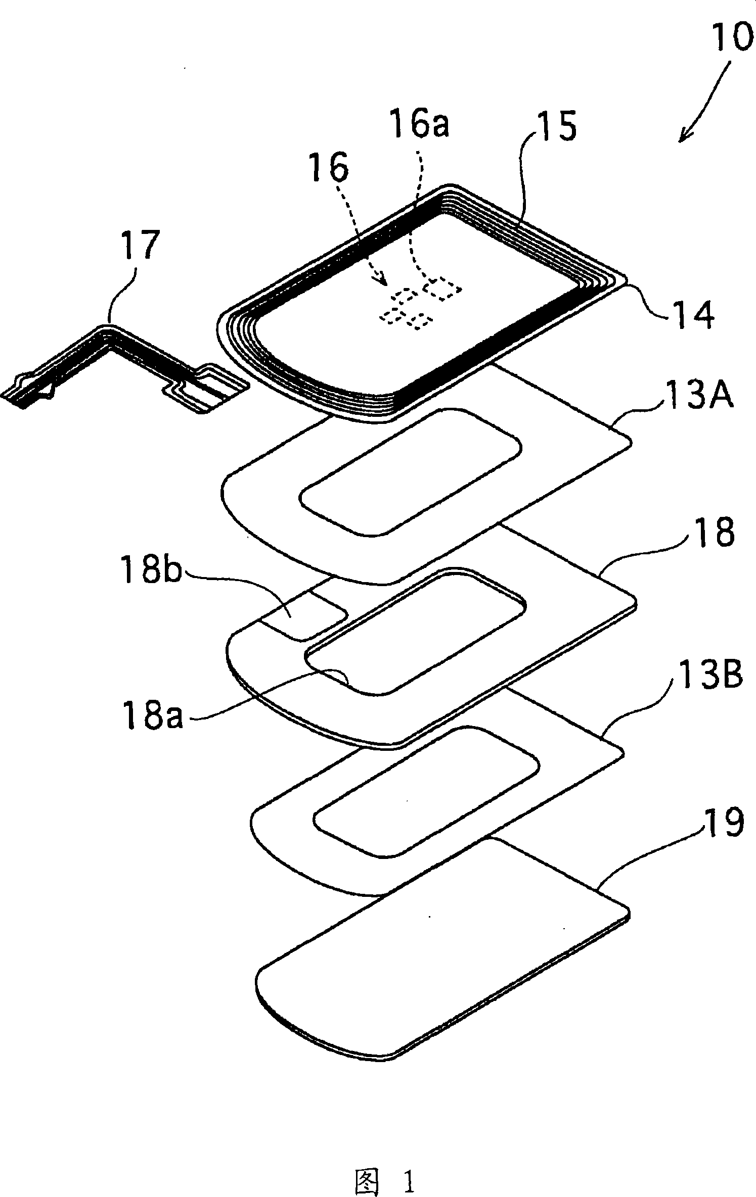
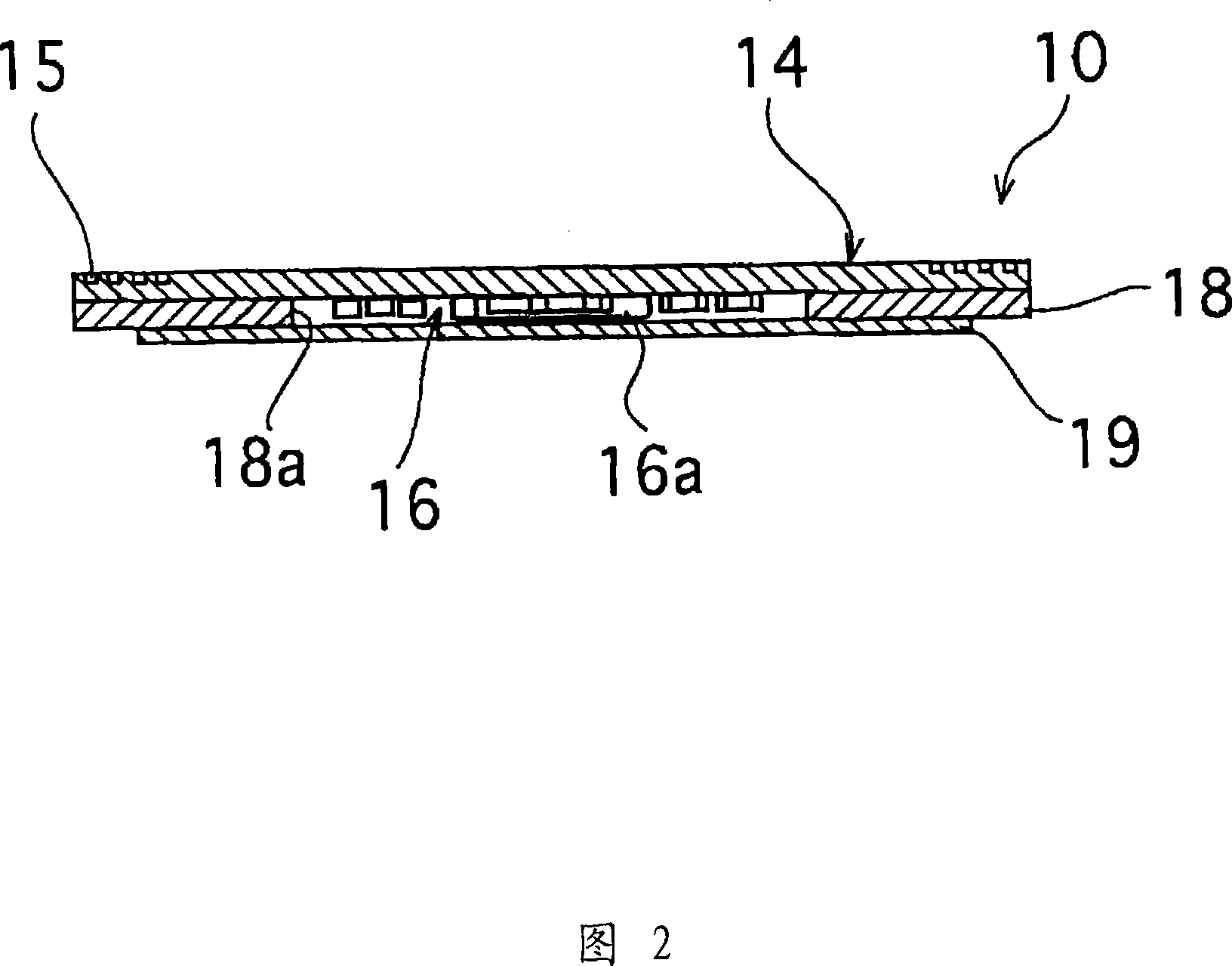
[0051] 1 and 2 are an exploded perspective view and a sectional side view showing the structure of an antenna module 10 for contactless data communication according to an embodiment of the present invention.

[0052] The antenna module 10 is constituted by stacking a substrate 14 as a support member, a magnetic core member 18 , and a metal shield plate 19 . The substrate 14 and the magnetic core part 18 are stacked with a double-sided adhesive sheet 13A sandwiched therebetween, and the magnetic core part 18 and the metal shield plate 19 are stacked with a double-sided adhesive sheet 13B sandwiched therebetween. In FIG. 2, the double-sided adhesive sheets 13A and 13B are omitted.

[0053] The substrate 14 is an insulating flexible substrate made of a plastic film of polyimide, polyethylene terephthalate (PET), polyethylene naphthalate (PEN), or the like. The substrate 14 can also b...


PUM


Abstract

The invention provides an antenna module-use magnetic core member capable of improving a communication distance without increasing a module thickness, and an antenna module and a portable information terminal provided with this. An antenna module (1) comprising a sheet-formed magnetic core member (4) layered on a looped antenna coil-formed antenna substrate (2), wherein a magnetic core member (4) having a performance index, expressed by mu' * Q, of 300 or higher is used when Q is a reciprocal of a loss factor (tan delta=mu'' / mu') expressed by the real part mu' and the imaginary part mu'' of a complex permeability at a frequency used.

Description

technical field [0001] The present invention relates to a magnetic core member for an antenna module suitable for a non-contact IC tag using RFID (Radio Frequency Identification), an antenna module, and a portable information terminal equipped with the antenna module. Background technique [0002] Conventionally, non-contact IC cards and identification tags (hereinafter collectively referred to as "non-contact IC tags") employing RFID technology are known to have an information recording IC chip and a resonance capacitor electrically connected to an antenna coil. . The structure of the non-contact IC tag is as follows. Radio waves of a preset frequency are transmitted from the transmitting / receiving antenna of the reader / writer to the antenna coil to activate the non-contact IC tag by reading the data recorded in the IC chip according to the reading instruction during radio wave data communication. Information, or by judging whether the IC tag resonates with radio waves of...

Claims


Application Information

Patent Timeline
Patent Type & Authority Applications(China)
IPC IPC(8): H01Q7/06G06K19/07G06K19/077H01Q1/24
Inventor 秋保启高桥功菅原利明横田敏昭
Owner SONY CORP
Learn More