Flat grinding abrasive belt polishing machine
A technology of abrasive belt polishing and flat grinding, applied in the field of machinery, can solve the problems of cumbersome adjustment process, width limitation, time-consuming and labor-intensive, etc., and achieve the effect of wide applicability and easy operation
- Summary
- Abstract
- Description
- Claims
- Application Information
AI Technical Summary
Problems solved by technology
Method used
Image
Examples
Embodiment 1
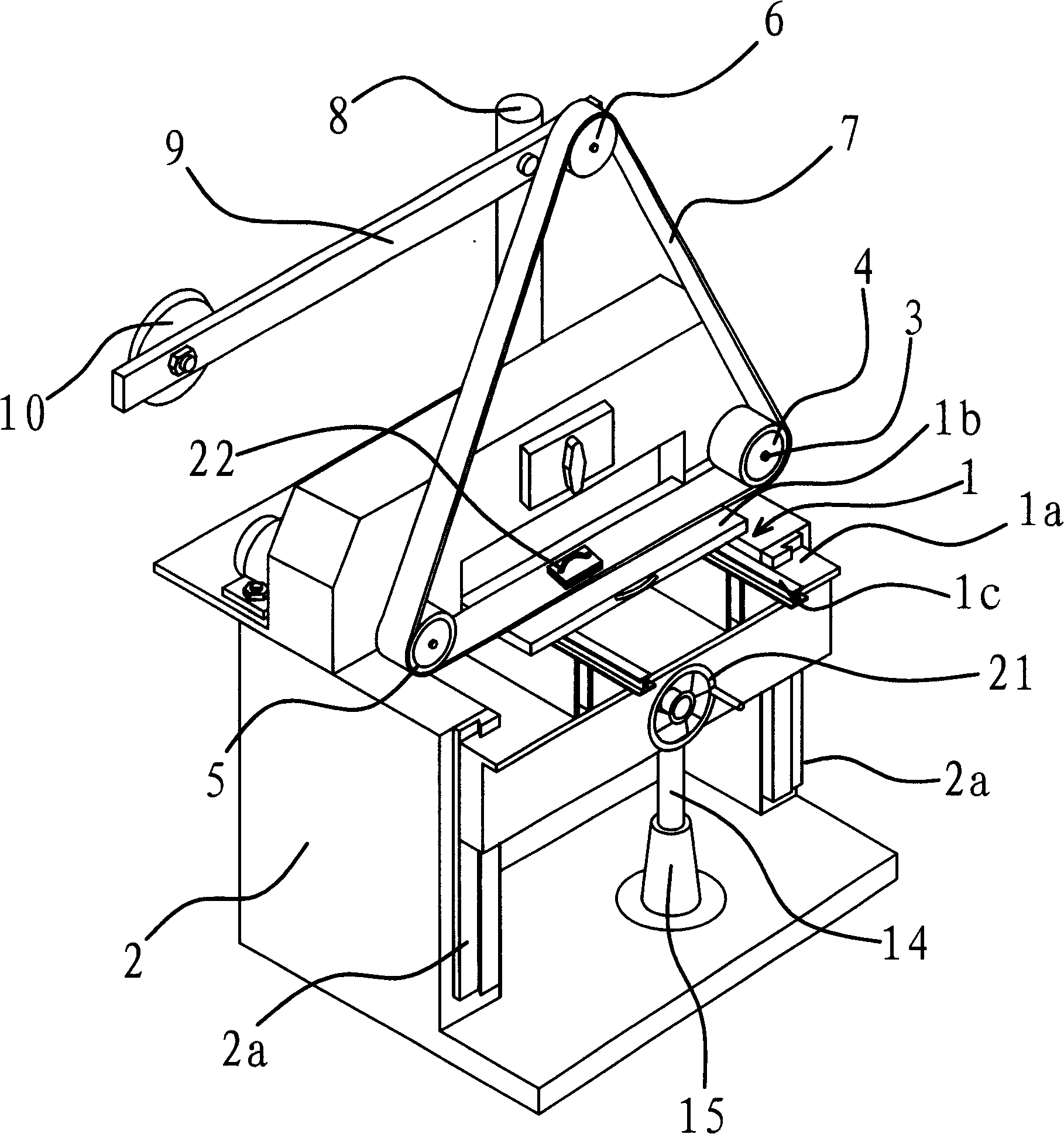
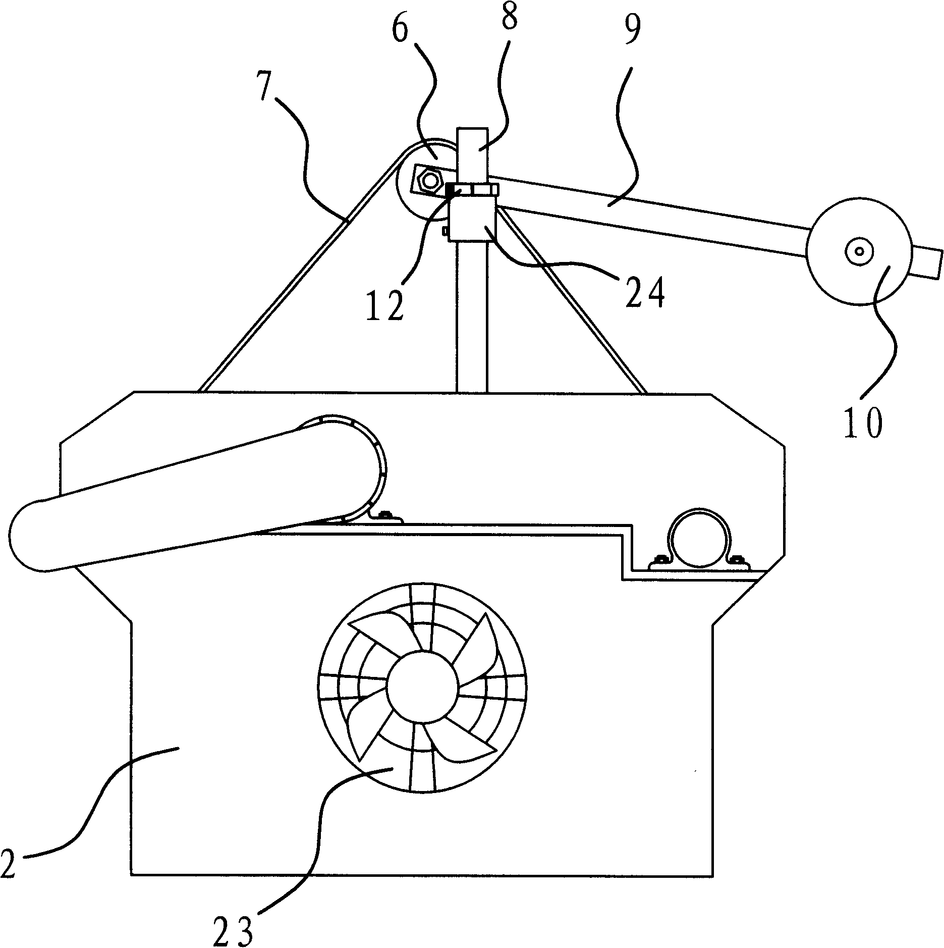
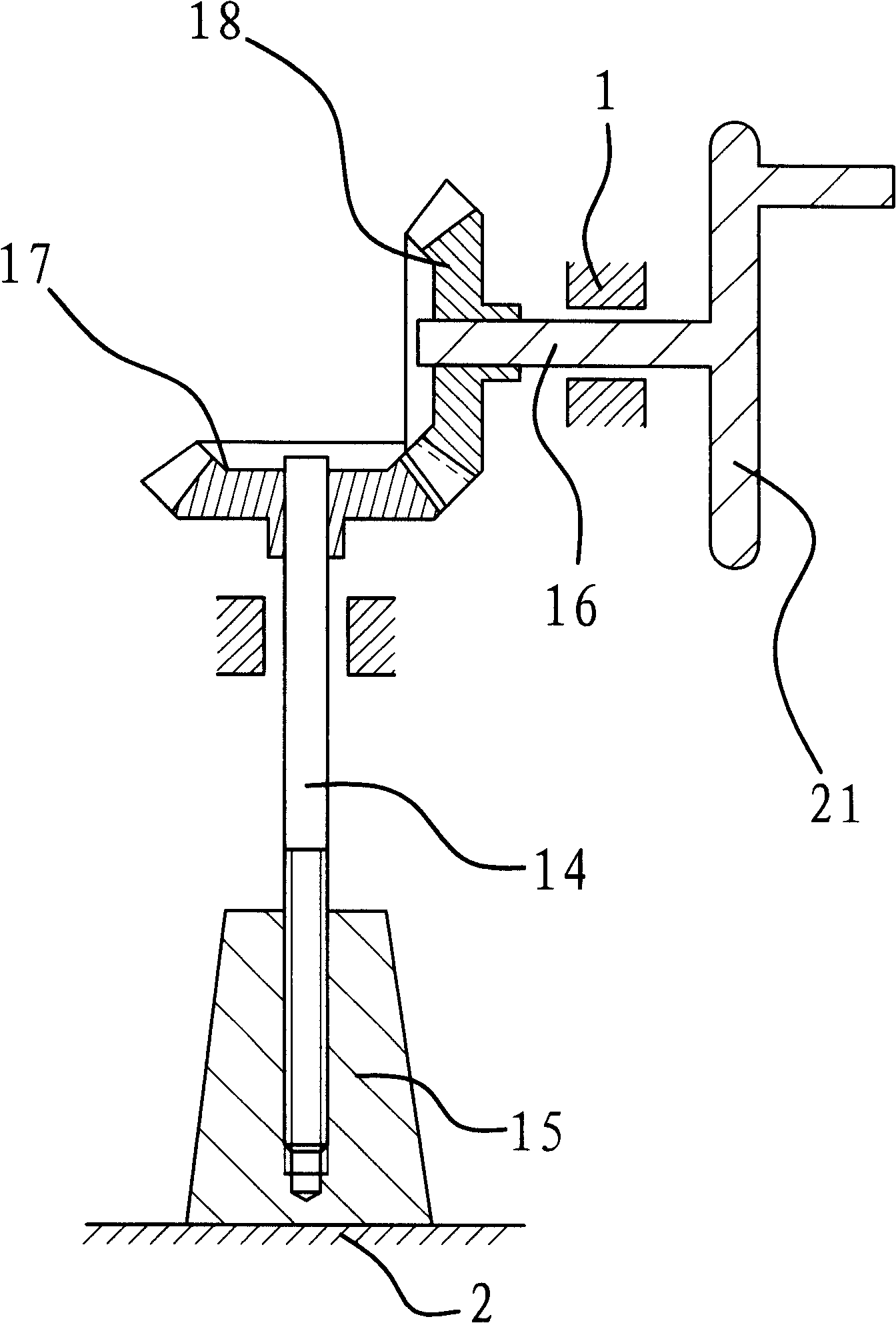
[0045] like figure 1 , figure 2 , image 3 , Figure 4 As shown, the flat abrasive belt polishing machine is used for polishing and polishing the workpiece. It includes a frame 2, which is provided with a workbench 1, a driving wheel 4, a driven wheel 5, a tensioning wheel 6 and an abrasive belt 7, and the abrasive belt 7 is sleeved on the above-mentioned driving wheel 4, driven wheel 5 and On the tensioning wheel 6, and the abrasive belt 7 is close to the above-mentioned workbench 1. Frame 2 is also provided with rotating shaft 3, and rotating shaft 3 is connected with power mechanism, can drive rotating shaft 3 to rotate under the effect of power mechanism, and above-mentioned driving wheel 4 just is fixedly connected on rotating shaft 3.
[0046] Abrasive belt 7 is used for the work surface of workpiece polishing, polishing treatment and workbench 1 is arranged oppositely, and is provided with adjustment mechanism between workbench 1 and frame 2, can make the workbench...
Embodiment 2
[0059] The structure and principle of this embodiment are basically the same as those of Embodiment 1, as Figure 5 As shown, the difference is that the adjustment mechanism for adjusting the lifting of the workbench is composed of a rack 19, a transmission gear 20 and a transmission rod 16. The rack 19 is fixedly connected with the above-mentioned workbench 1, and the rack 19 is vertically set in the vertical direction. The transmission rod 16 is axially fixed on the frame 2, the transmission gear 20 is fixedly connected to the transmission rod 16, and the transmission gear 16 is meshed with the above-mentioned rack 19.
[0060] Of course, the transmission rod 16 is also provided with a hand wheel 21, the rotation of the hand wheel 21 drives the transmission rod 16 to rotate, and the drive gear 20 and the rack 19 that are engaged drive the workbench 1 to go up and down.
Embodiment 3
[0062] The structure and principle of this embodiment are basically the same as those of Embodiment 1, as Image 6 As shown, the difference is that the rear end of the adjustment rod 9 is provided with several adjacent adjustment holes 9a. When the above-mentioned tension wheel 6 is connected in any one of the adjustment holes 9a, the rear end of the adjustment rod 9 is adjusted. The hem force changes. Accordingly, the tension of the abrasive belt 7 is adjusted.
PUM
 Abstract
Description
Claims
Application Information
 - R&D
- Intellectual Property
- Life Sciences
- Materials
- Tech Scout
- Unparalleled Data Quality
- Higher Quality Content
- 60% Fewer Hallucinations
Browse by: Latest US Patents, China's latest patents, Technical Efficacy Thesaurus, Application Domain, Technology Topic, Popular Technical Reports.
© 2025 PatSnap. All rights reserved.Legal|Privacy policy|Modern Slavery Act Transparency Statement|Sitemap|About US| Contact US: help@patsnap.com


