Hydraulic drive apparatus of work machine

A technology for working machines and driving devices, applied in the direction of fluid pressure actuation devices, mechanical equipment, machines/engines, etc., can solve problems such as fuel cost reduction, reduction, fuel cost difference, etc. fee reduction effect

Active Publication Date: 2007-04-18
KOMATSU LTD
View PDF3 Cites 10 Cited by
  • Summary
  • Abstract
  • Description
  • Claims
  • Application Information

AI Technical Summary

Problems solved by technology

[0012] However, when working with a hydraulic excavator, for example, when excavating soil and sand, the excavated soil and sand are pocketed into a bucket, the boom is raised while the upper rotating body is rotated, and the soil and sand in the bucket are piled into a dump truck. There is a big difference in the required pump output when the boom is lowered and rotated in order to enter the next operation cycle after the soil and sand are piled up.
[0013] However, in the hydraulic drive system of Patent Document 1, when the series of work actions are performed in the state shown in FIG. , in this series of operations, even when the operating conditions are such that the output of the hydraulic pump is hardly required, the engine is used around the engine speed Na at which the fuel consumption rate is high, so there is a problem of unnecessary fuel consumption.
Also, the operator switches between the heavy excavation mode shown in FIG. 10(a) and the excavation mode (leveling mode) shown in FIG. This operation is virtually impossible, so there is a problem that a sufficient fuel cost reduction effect cannot be obtained in actual work in which working conditions change from time to time.
[0014] In addition, in the hydraulic drive device of the above-mentioned Patent Document 2, when performing the series of operations, as shown in FIG. However, in this series of operations, the engine operates within the range of the fuel consumption rate on the adjustment curve Ra (engine speed NA~Nd), and there is a problem of poor fuel consumption
[0015] In addition, in the hydraulic drive device of Patent Document 3, the target output torque point at which the minimum fuel consumption is obtained is changed by the operator switching the operation mode. It is practically impossible to change the target output torque point to obtain the minimum fuel consumption according to the working conditions that change constantly. Therefore, in the actual work where the working conditions change constantly, there is a possibility that a sufficient effect of reducing fuel consumption cannot be obtained. The problem
[0016] In addition, in the engine control mechanism for a construction machine disclosed in Patent Document 4, the engine can be used in a region where the fuel consumption rate is low when the operating amount of the operating lever device is small and the engine speed is hardly required at light loads. When the operation amount of the device is large and the load requires high engine speed, the engine speed can be increased first to ensure workability. However, when the operation amount of the control lever device is changed rapidly, the engine speed changes frequently, but the working machine does not Following the up and down of the engine speed, there is a problem that it does not match the operator's operating feeling

Method used


Image

  • Hydraulic drive apparatus of work machine
  • Hydraulic drive apparatus of work machine
  • Hydraulic drive apparatus of work machine

Examples


Embodiment Construction

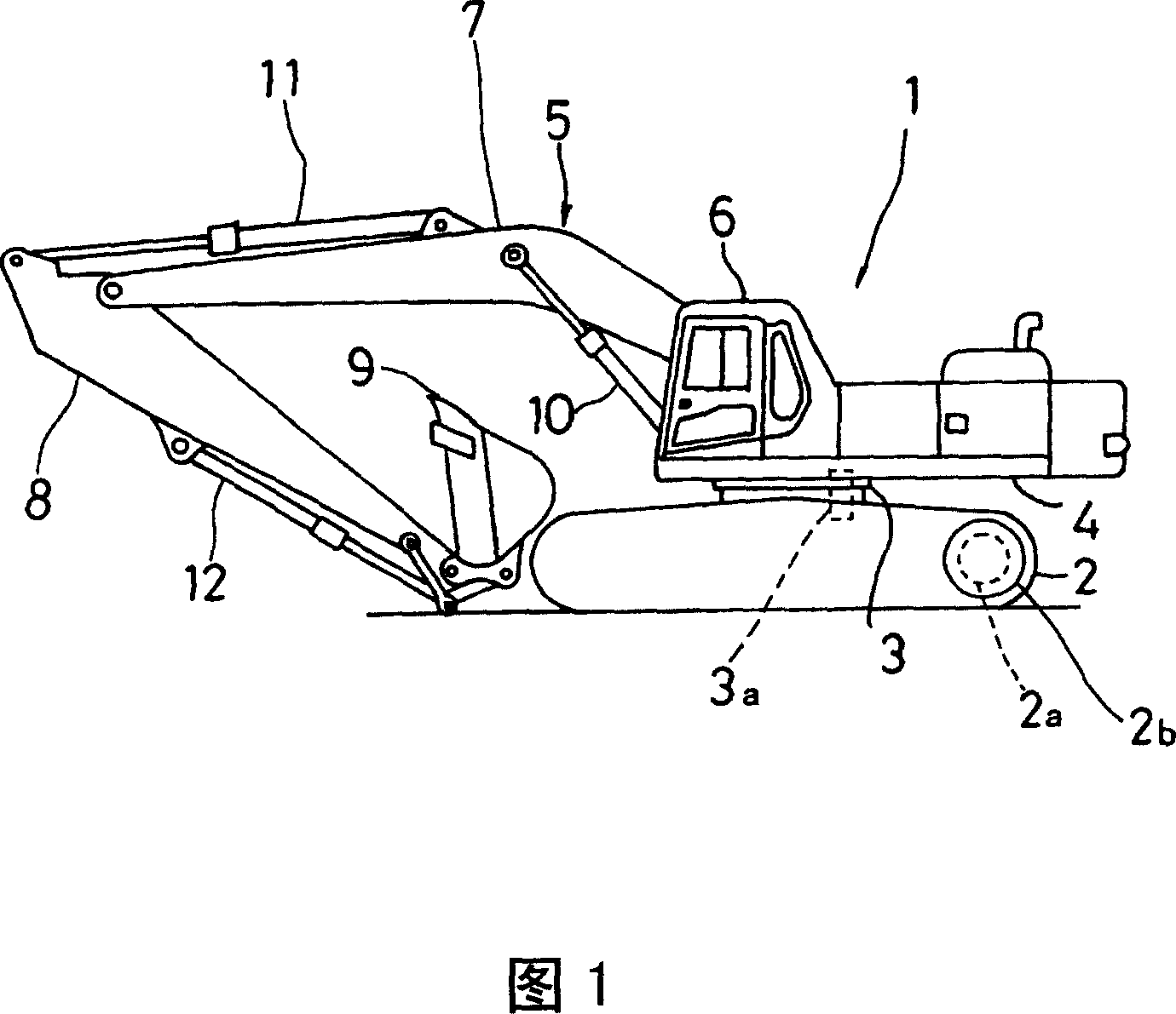
[0041] Next, specific embodiments of a hydraulic drive system for a working machine according to the present invention will be described with reference to the drawings. In addition, this embodiment is an example in which the present invention is applied to a hydraulic excavator as a work machine.

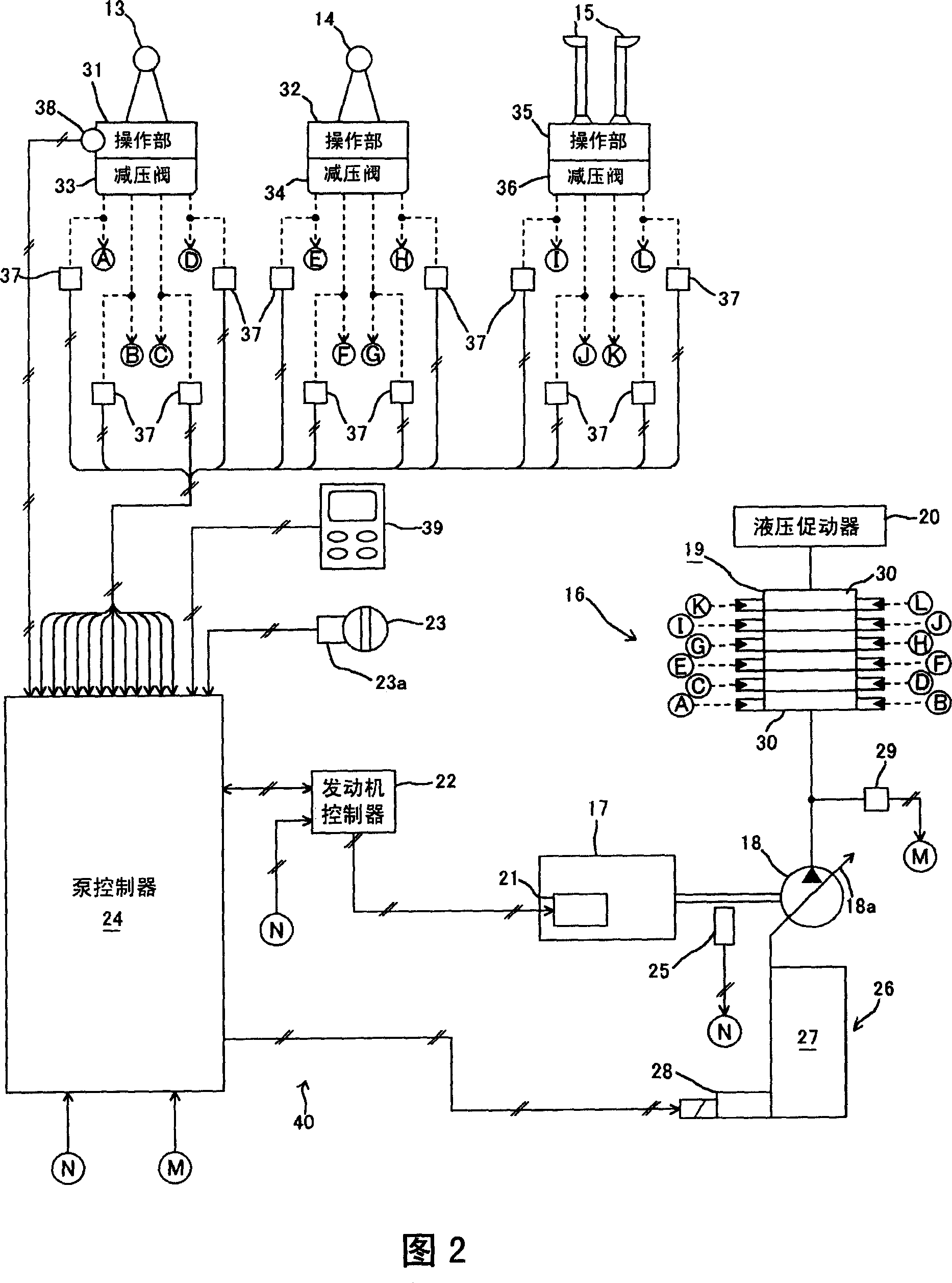
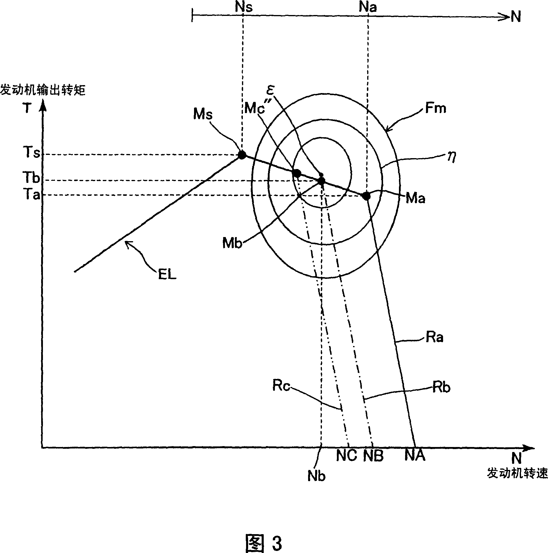
[0042] FIG. 1 shows a side view of a hydraulic excavator according to an embodiment of the present invention. In addition, FIG. 2 shows an overall schematic system configuration diagram of a hydraulic drive device according to this embodiment, FIG. 3 shows an output torque characteristic diagram of an engine according to this embodiment, and FIG. 4 shows the functions of an engine-hydraulic pump control device according to this embodiment. block diagram.

[0043] A hydraulic excavator 1 according to the present embodiment is provided with, as shown in FIG. 1 , an undercarriage 2 provided with a traveling device 2b driven by a traveling hydraulic motor 2a, and a swivel device 3 driv...


PUM


Abstract

A hydraulic drive apparatus of a work machine capable of securely providing a fuel cost reduction effect also in an actual work in which working conditions vary every hour. The apparatus comprises a working condition discriminating part (41) discriminating working conditions and a hydraulic pump controller (40b) controlling the absorption torque of a hydraulic pump (18). When the working conditions discriminated by the working condition discriminating part (41) are specific ones, the hydraulic pump controller (40b) controls the absorption torque of the hydraulic pump (18) so that the absorption torque characteristic line of the hydraulic pump (18) matches the absorption torque characteristic line (PLb) of the hydraulic pump which makes equal the output torque of an engine (17) to the absorption torque of the hydraulic pump (18) at an engine output torque point (Mb) where a fuel consumption is approximately minimized.

Description

technical field [0001] The present invention relates to a hydraulic drive device preferably mounted on a working machine such as a hydraulic excavator. Background technique [0002] As such a conventional hydraulic drive device, for example, those proposed in Patent Documents 1 to 3 are known. In the hydraulic drive device of Patent Document 1, the engine output torque characteristic and the hydraulic pump absorption torque characteristic are respectively set according to the work mode selected by the operator. In addition, in the hydraulic drive device of Patent Document 2, by detecting a specific operating state of the control lever, it is detected that the working machine is in a specific operating state, and when the working machine is in a specific operating state, the hydraulic pump is absorbed. The maximum value of the torque is set to a prescribed value consistent with this operating state. In addition, in the hydraulic drive device of Patent Document 3, in any one...

Claims


Application Information

Patent Timeline
Patent Type & Authority Applications(China)
IPC IPC(8): F15B11/00E02F9/22F02D29/04
CPCE02F9/2235E02F9/2246E02F9/2296F02D29/04B60W2510/305F15B11/00E02F9/22
Inventor 成濑真己
Owner KOMATSU LTD
Why Eureka
Try Eureka