Eureka AIR delivers breakthrough ideas for toughest innovation challenges, trusted by R&D personnel around the world.

Rod insertion pressure bearing type solar energy water heater

A solar water heater, pressure-bearing technology, applied in the direction of solar collectors, solar thermal energy, solar thermal power generation, etc., can solve the problems of water freezing in the tube, affecting heat transfer, and poor bathing comfort, so as to improve the heat conduction speed and avoid explosion. Tubes, the effect of improving heat transfer efficiency

Inactive Publication Date: 2007-04-18
尚诚德
View PDF0 Cites 3 Cited by
  • Summary
  • Abstract
  • Description
  • Claims
  • Application Information

AI Technical Summary

Problems solved by technology

[0003] 1. Only the rubber ring is used to seal the vacuum heat collecting tube and the water tank, which cannot fundamentally solve the problem of water leakage and cannot withstand the water pressure of the pipe network;
[0004] 2. The vacuum heat collecting tube has poor pressure resistance and is explosive under the action of the water pressure of the pipe network
If the thickness of the glass of the vacuum heat collecting tube is increased to improve the pressure resistance, the heat absorption capacity of the vacuum heat collecting tube will be greatly reduced;
[0005] 3. When the vacuum heat collecting tube cannot absorb heat in continuous cloudy days in winter, the water in the tube will freeze and cause the tube to burst
[0006] 4. Since it is not under pressure, when the hot water it releases is mixed with tap water, it is easy to appear hot and cold due to unstable tap water pressure;
[0007] 5. The difference between the liquid level of the water tank and the water outlet leads to the difference in the water pressure of the water outlet. The water pressure is generally low and the bathing comfort is poor;
[0008] 6. The inner wall of the vacuum heat collecting tube is easy to form scale, which affects the heat transfer;
[0009] 7. Once the vacuum heat collecting tube is damaged, it will affect the operation of the whole machine
There are two deficiencies in this structural form. First, the connection between the heat pipe and the water tank is flexibly connected. Whether it is sealed by a sealing ring or a threaded sealing connection, the problem of water leakage cannot be fundamentally solved; secondly, the inner sleeve is used. The structural form of the tube is still filled with liquid water, so the excellent thermal conductivity of the metal material is not maximized, and the thermal conductivity is not maximized.

Method used


Image

  • Rod insertion pressure bearing type solar energy water heater
  • Rod insertion pressure bearing type solar energy water heater
  • Rod insertion pressure bearing type solar energy water heater

Examples


Embodiment Construction

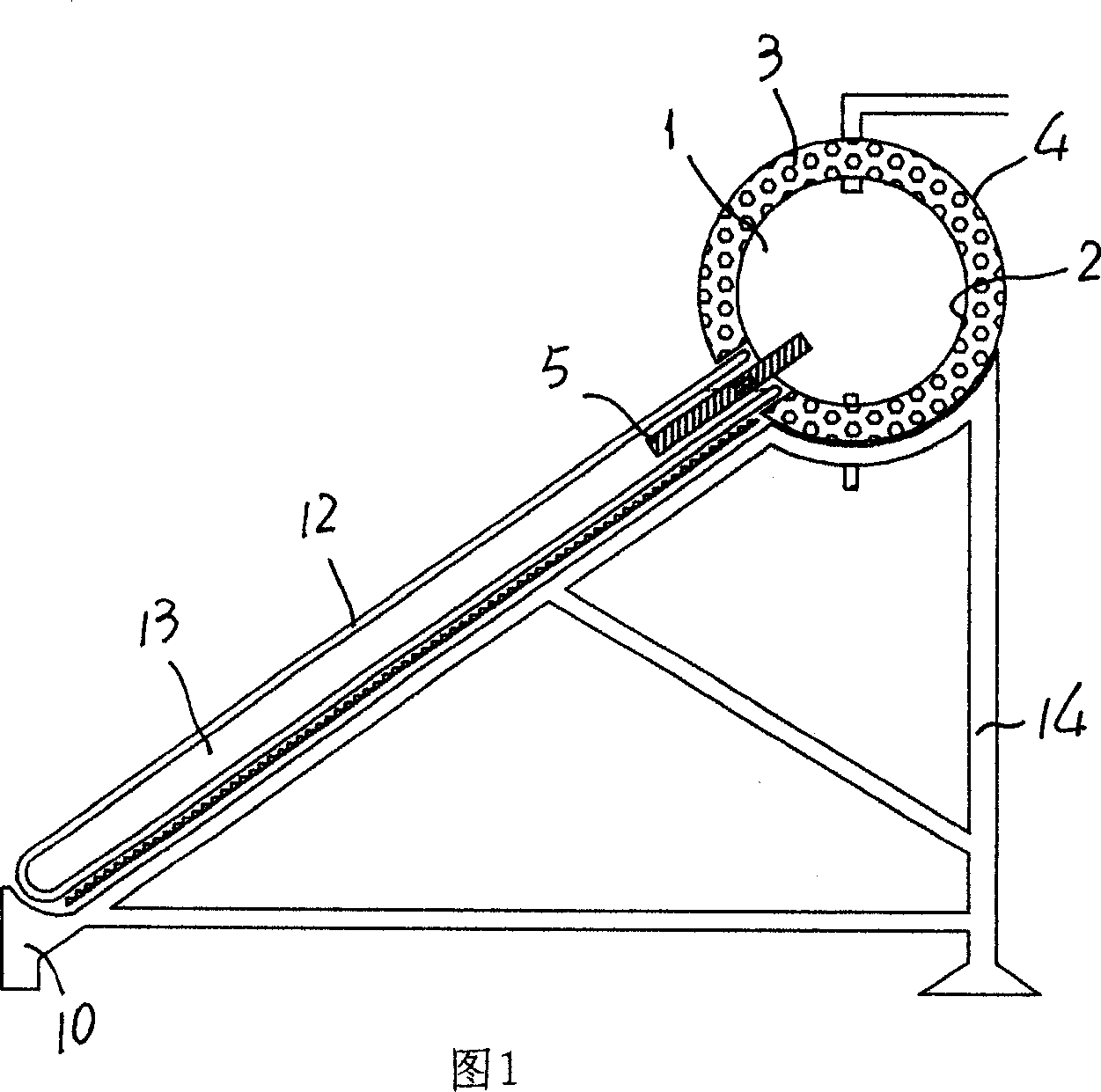
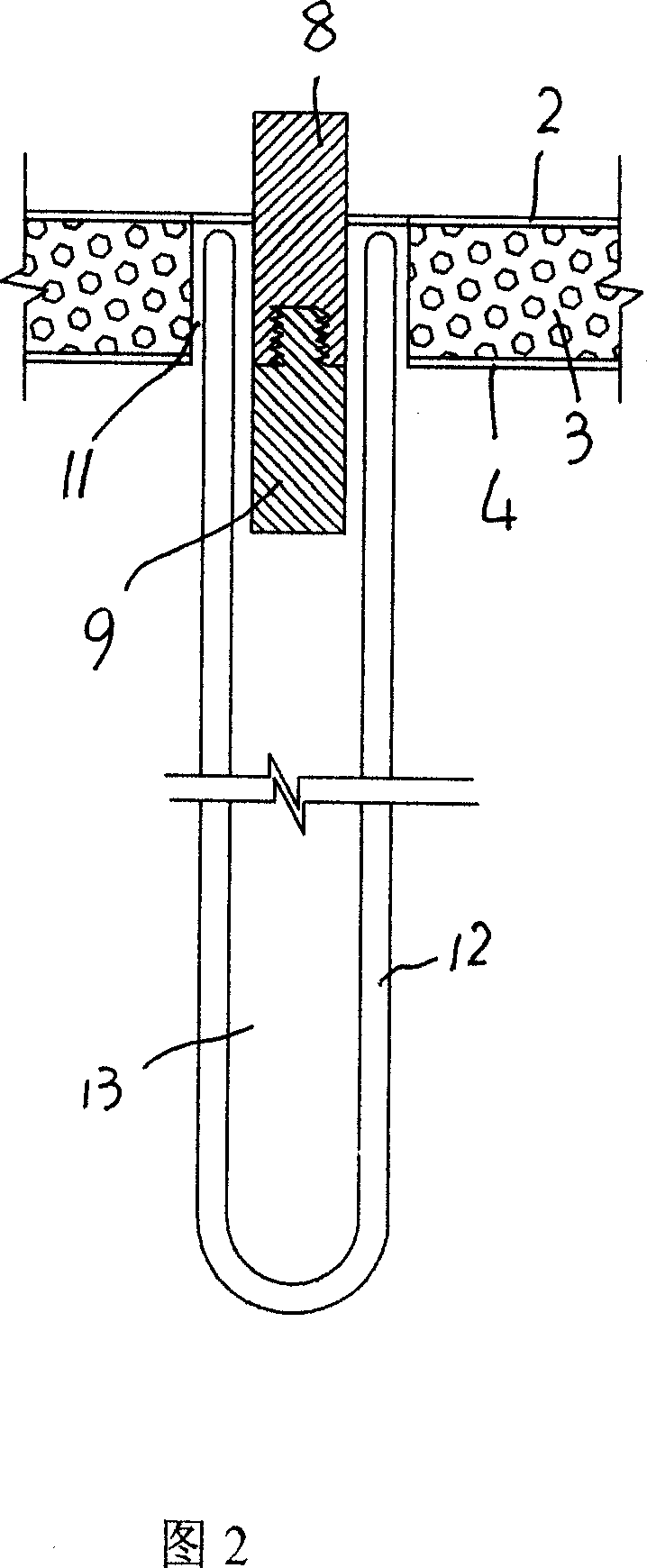
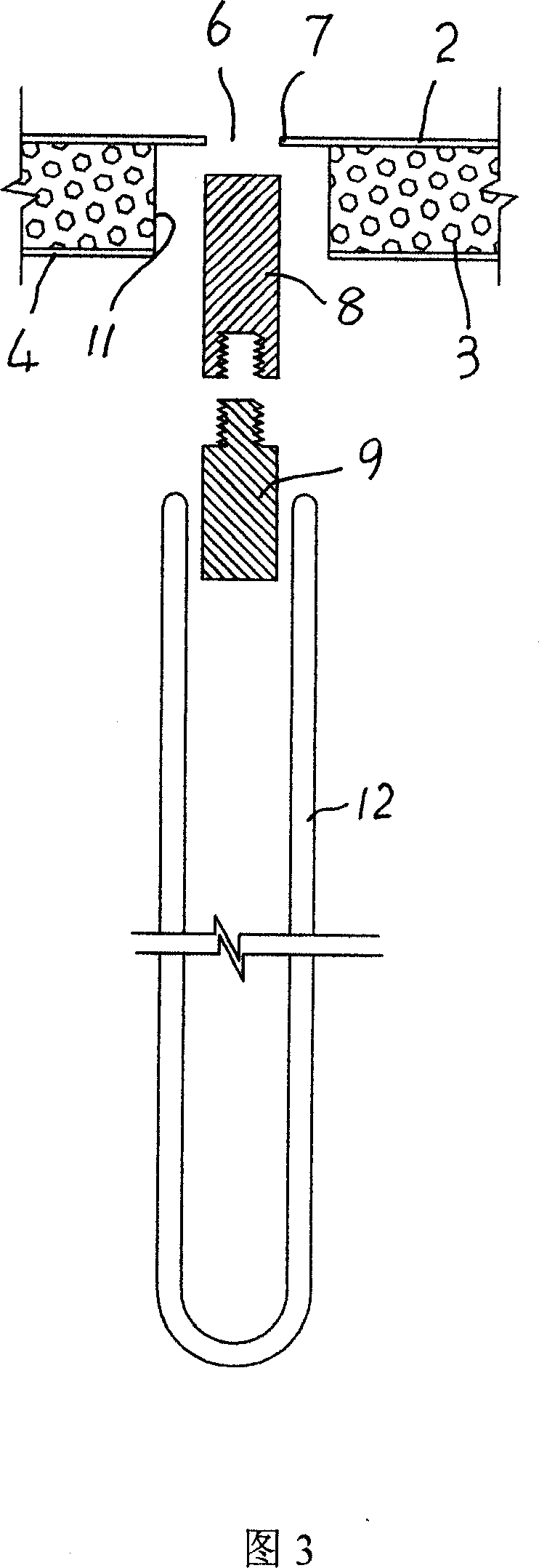
[0031] Referring to Fig. 1, a pressurized water tank 1 and a vacuum heat collecting tube 12 are adopted, and a metal heat conduction rod 5 is arranged, and the metal heat conduction rod 5 is embedded in the water tank liner 2 with its upper embedded section 8, and inserted with its lower extended section 9. In the vacuum heat collecting tube 12, the metal heat conducting rod 5 is used to block the metal heat conducting rod insertion port 6 on the water tank liner 2 at the position of the vacuum heat collecting tube 12, and the nozzle of the vacuum heat collecting tube 12 is placed in the pressurized water tank 1 In the reserved opening 11 of the water tank insulation layer 3 and the shell 4.

[0032] In specific implementation, the metal heat-conducting rod 5 seals the metal heat-conducting rod insertion port 6 on the water tank liner 2 by welding it to the water tank liner 2 .

[0033] In order to facilitate assembly and transportation, the embedded section 8 and the extensio...


PUM


Abstract

A solar water heater adopts a pressure-bearing water tank and a vacuum heat-collecting pipe and it is characterized by setting a metal heat-conducting bar. The insert section in the upper part of the metal heat-conducting bar is plugged in the inner container of the water tank and the extension section in the lower part of the metal heat-conducting bar is plugged in the vacuum heat-collecting pipe. The inserting mouth of the metal heat-conducting bar on the inner container of the water tank forms a plugging and the mouth of the vacuum heat-collecting pipe is disposed in the insulating layer of the pressure-bearing water tank and in the preset mouth of the casing.

Description

technical field [0001] The invention relates to a solar water heater, in particular to a pressurized solar water heater capable of realizing rapid transfer of heat energy. Background technique [0002] The existing non-pressurized solar water heater has several defects because the open end of the vacuum heat collecting tube is directly placed in the water tank: [0003] 1. Only the rubber ring is used to seal the vacuum heat collecting tube and the water tank, which cannot fundamentally solve the problem of water leakage and cannot withstand the water pressure of the pipe network; [0004] 2. The vacuum heat collecting tube has poor pressure resistance and is explosive under the action of the water pressure of the pipe network. If the thickness of the glass of the vacuum heat collecting tube is increased to improve the pressure resistance, the heat absorption capacity of the vacuum heat collecting tube will be greatly reduced; [0005] 3. When the vacuum heat collecting tu...

Claims


Application Information

Patent Timeline
IPC IPC(8): F24J2/05F24J2/30F24S10/40F24S10/30
CPCY02E10/44
Inventor 尚诚德徐宝
Owner 尚诚德
Why Eureka
Eureka Blog
Learn More