
Electromagnetic suspension and driving space micro motion method and mechanical device

An electromagnetic levitation and mechanical device technology, applied in the direction of magnetic attraction or thrust holding device, electrical components, etc., can solve the problems of low degree of freedom, small movement range of micro-manipulator, slow response, etc.

Inactive Publication Date: 2007-03-28
ZHEJIANG SCI-TECH UNIV
View PDF0 Cites 13 Cited by
  • Summary
  • Abstract
  • Description
  • Claims
  • Application Information

AI Technical Summary

Problems solved by technology

[0003] Aiming at the deficiencies of current micro-manipulators such as small motion range, low degree of freedom, and slow response, the purpose of the present invention is to provide a space micro-motion method and mechanical device for electromagnetic levitation and drive

Method used


Image

  • Electromagnetic suspension and driving space micro motion method and mechanical device

Examples


Embodiment Construction

[0014] The present invention will be further described below in conjunction with drawings and embodiments.

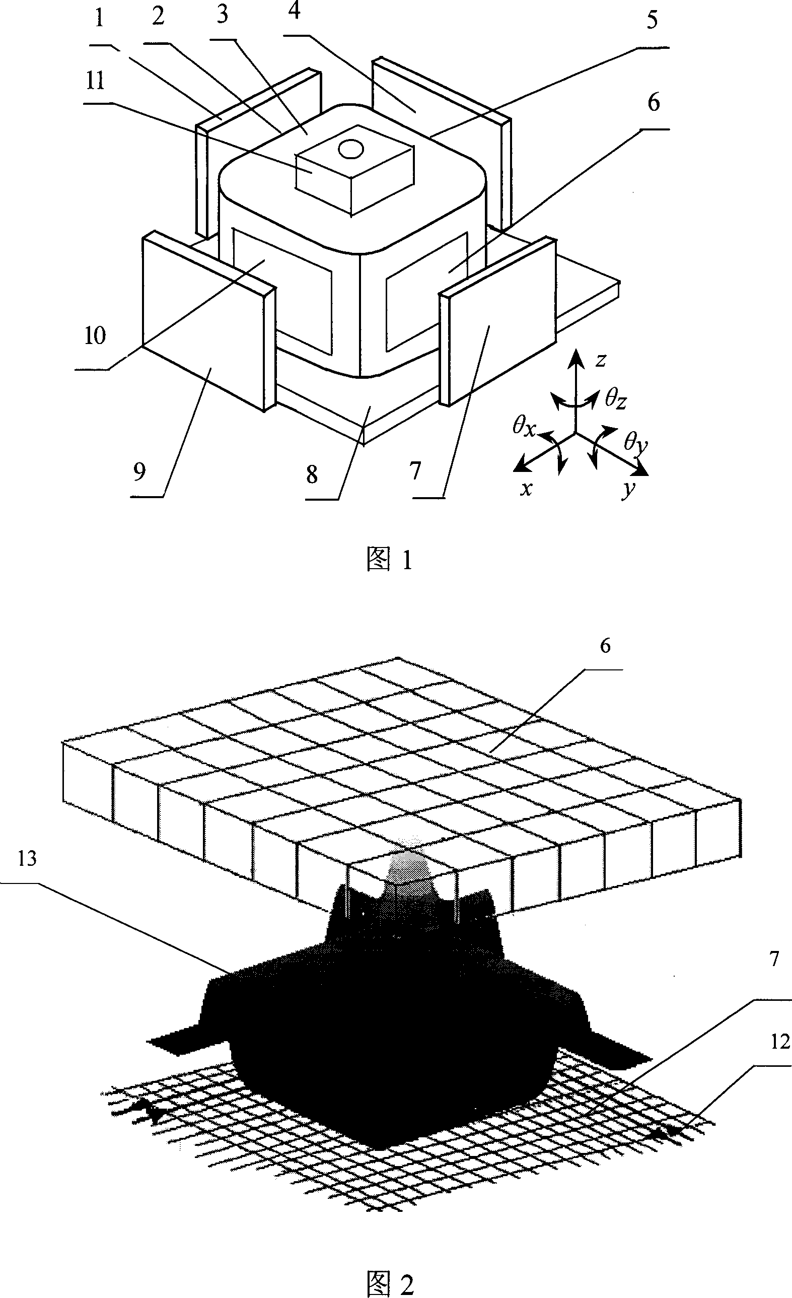
[0015] As shown in Figure 1, the present invention includes four groups of wire arrays 1, 4, 7, 9, four groups of permanent magnet arrays 2, 5, 6, 10, a moving body 3, and a group of permanent magnetic arrays under the bottom surface of the moving body, A group of wire arrays 8 under the bottom surface of the moving body, and a micromanipulator holder 11; the micromanipulator is installed on the micromanipulator holder 11, and the micromanipulator holder 11 is fixed on the moving body 3. A set of permanent magnet arrays are respectively embedded in the sides and bottom, and a set of wire arrays are arranged correspondingly to the four sides and bottom of the moving body 3 embedded with a set of permanent magnet arrays. That is, the first group of permanent magnet array 2 and the first group of wire array 1, the second group of permanent magnet array 5 and the second gro...


PUM


Abstract

The micro-operator is fixed on the moving object. A group of permanent magnet arrays (PMA) are buried into the bottom and four sides of the object. A group of wire arrays are set corresponding to each group of PMA. Whenever the electric current flows through the wire arrays under the moving object, the electric-magnetic field produced by the wire arrays interacts with the magnetic field produced by the PMA. It causes the moving object floating. By means of changing the direction and magnitude of the current in each group of the wire arrays, the 6-dimension space micro-movement needed by the micro-operator can be realized. This is such a Nano-lever movement, which has advantages of great working range, high precision and fast response time. This apparatus suits mainly for fields as the micro mechanical-electric system, the biology engineering, IC chip manufacture technique, the molecule and atom control, etc.

Description

technical field [0001] The invention relates to an electromagnetic levitation and driving space micro-motion method and a mechanical device. Background technique [0002] At present, various micromanipulator drive technologies, although there are many micro drive methods and drives, such as piezoelectric drives, electrostatic drives and shape memory alloy drives, but research on micro manipulator drives often only discusses and focuses on improving motion accuracy or Resolution is a single parameter, although the motion accuracy or resolution can reach a higher index, with nanometer or even sub-nanometer motion accuracy and resolution, but their range of motion is very small, generally limited to small objects below the micron level. The range of motion, that is, the existing various micro-actuation methods cannot take into account the contradiction between high motion accuracy and large motion range. Secondly, the current various micromanipulator drive technologies all use...

Claims


Application Information

Patent Timeline
IPC IPC(8): H02N15/00
Inventor 陈本永杨涛潘科荣孙政荣王俊茹
Owner ZHEJIANG SCI-TECH UNIV
Learn More