
Multi-optical-fiber port platform and mfg. method

A multi-fiber, multi-fiber technology, applied in the direction of bundle optical fiber, light guide, optics, etc., can solve the problems of limited application scope, high cost, unsuitability, etc., and achieve the effect of wide application scope, simple manufacturing process and low cost.

Active Publication Date: 2007-03-28
中贝光电科技(湖北)有限公司
View PDF0 Cites 11 Cited by
  • Summary
  • Abstract
  • Description
  • Claims
  • Application Information

AI Technical Summary

Problems solved by technology

The first is to construct a multi-fiber port by placing each optical fiber in a high-precision glass capillary. The fiber port constructed by this scheme can provide a limited number of ports. Generally, only three-fiber ports can be provided. When applied to four For optical fiber or above, the existing precision processing device cannot meet the practical requirements because it cannot meet the processing accuracy required by the capillary hole
The second solution is to use high-precision glass, silicon V-shaped grooves or polymer square ferrules to construct multi-fiber ports. Since each optical fiber is arranged in the V-shaped groove or polymer square ferrule, its arrangement is Linear arrangement structure, when used in many systems that require micro-optical components such as lenses, because its inherent fiber arrangement structure characteristics will cause high transmission loss, it is not suitable for most multi-fiber systems that require micro-optical components
The third is to use the method of mechanical impact assembly to construct the multi-fiber port. In this scheme, mechanical components are used to impact the metal parts surrounding multiple optical fibers, so that the multi-fiber port is assembled by the metal parts to tightly bundle the multi-fibers. The resulting The optical fiber of the multi-fiber port is subject to greater stress due to being easily squeezed or affected by temperature changes, resulting in low reliability of the multi-fiber system
[0004] In addition, the multi-fiber ports that can only provide a limited number of optical fibers according to the known technology are more restricted in their application range, and the cost is relatively high

Method used


Image

  • Multi-optical-fiber port platform and mfg. method
  • Multi-optical-fiber port platform and mfg. method
  • Multi-optical-fiber port platform and mfg. method

Examples


Embodiment Construction

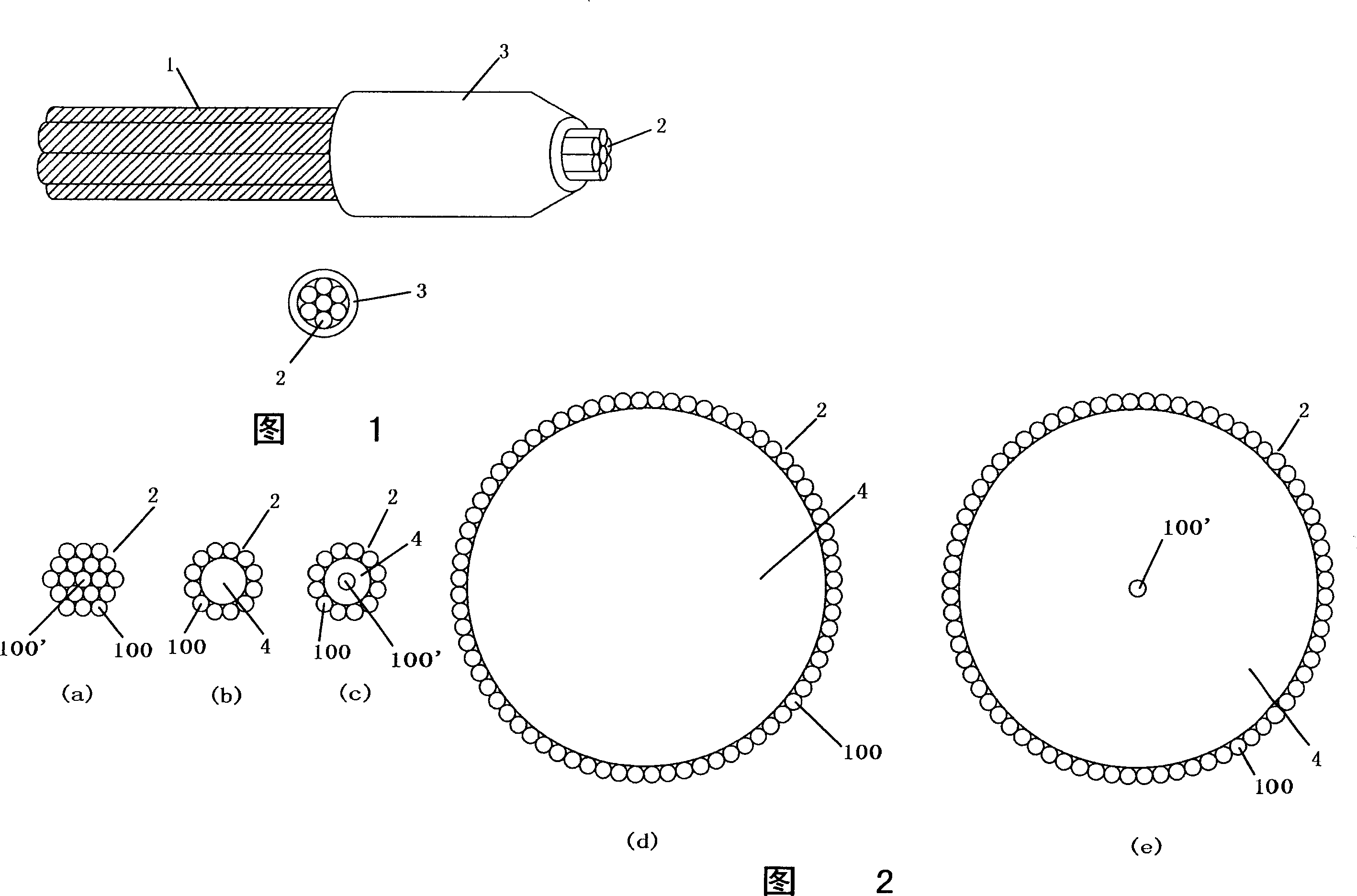
[0045] Fig. 1 has illustrated the multi-fiber port platform provided by the present invention, comprises the multiple optical fiber 1 that contains coating, comprises the optical fiber bundle 2 of the multiple optical fiber that removes coating at one end of multiple optical fiber 1 and ferrule 3, and optical fiber bundle 2 The gaps between the multiple optical fibers in the optical fiber bundle are sub-micron, the gap between the main body of the optical fiber bundle 2 is occupied by optical thermosetting glue or ultraviolet glue, the entire optical fiber bundle 2 is accommodated in the ferrule 3, and can be heated It is fixed in the ferrule 3 by means of solid glue or ultraviolet glue.

[0046]The fiber optic bundle 2 can have various cross-sectional shapes. In Fig. 2 (a), the optical fiber bundle 2 is formed by 18 optical fibers 100 surrounding the central optical fiber 100'; Material 4 can be glass rod, glass filament, silicon rod, silicon filament, ceramic rod or ceramic...


PUM


Abstract

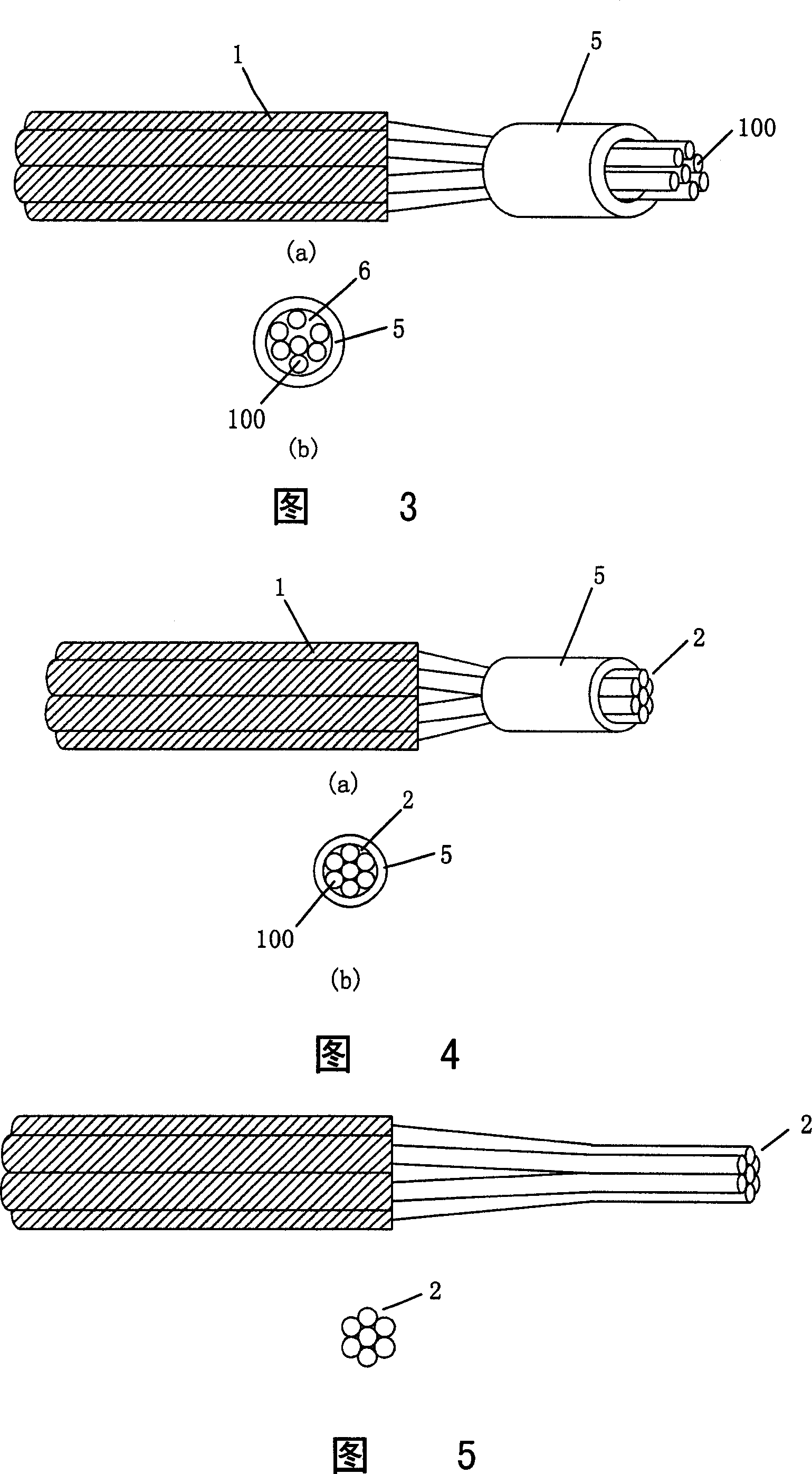
The invention provides the multi-optical port table including the insert core and the optical fiber bundle which the space between the many optical fibers is the sub-micron grade. The method includes: first to remove the covered layer of the optical fiber and cover the heat-shrinkable sleeving on it, the overlapping region is coated with the optical hot setting adhesive; then to heat the heat-shrinkable sleeving until the space between the optical fiber is sub-micron grade; it removes the heat-shrinkable sleeving after cooling it and inserts it into the insert core and fixes it by the ultraviolet glue or the optical hot setting adhesive to construct the tail fiber of the multi-optical fiber; the ultraviolet glue can instead the optical hot setting adhesive, so it can be solidified by the violet solidifying lamp. Last to polish or cut the tail fiber of the optical fiber bundle to construct the multi-optical port table. The invention has the high reliability and small size, but cost little.

Description

technical field [0001] The invention relates to an optical fiber port, in particular to a multi-fiber port platform and a manufacturing method thereof. Background technique [0002] For new applications and requirements, especially with the advent of the fiber-to-the-home, building, curb and desktop (FTTX) era, under the premise of maintaining good reliability, the new multi-fiber system equipment is obviously moving towards lower The development of technology cost and smaller volume requires that the multi-fiber ports constituting the new system equipment should be designed with good reliability, low cost and small volume. [0003] There are generally three known existing methods for constructing multi-fiber ports and the multi-fiber ports formed by this method. The first is to construct a multi-fiber port by placing each optical fiber in a high-precision glass capillary. The fiber port constructed by this scheme can provide a limited number of ports. Generally, only three...

Claims


Application Information

Patent Timeline
IPC IPC(8): G02B6/36G02B6/04G02B6/26G02B1/00
CPCG02B6/403G02B6/04
Inventor 童朝阳张大庆
Owner 中贝光电科技(湖北)有限公司
Learn More