
Business flow protection method

A service flow and service technology, which is applied in the direction of data exchange, digital transmission system, electrical components, etc. through path configuration, and can solve problems such as inconsistent service flow status, non-setup, and service flow interruption.

Inactive Publication Date: 2007-03-14
JIANGSU HENGYUAN METAL MATERIALS
View PDF0 Cites 16 Cited by
  • Summary
  • Abstract
  • Description
  • Claims
  • Application Information

AI Technical Summary

Problems solved by technology

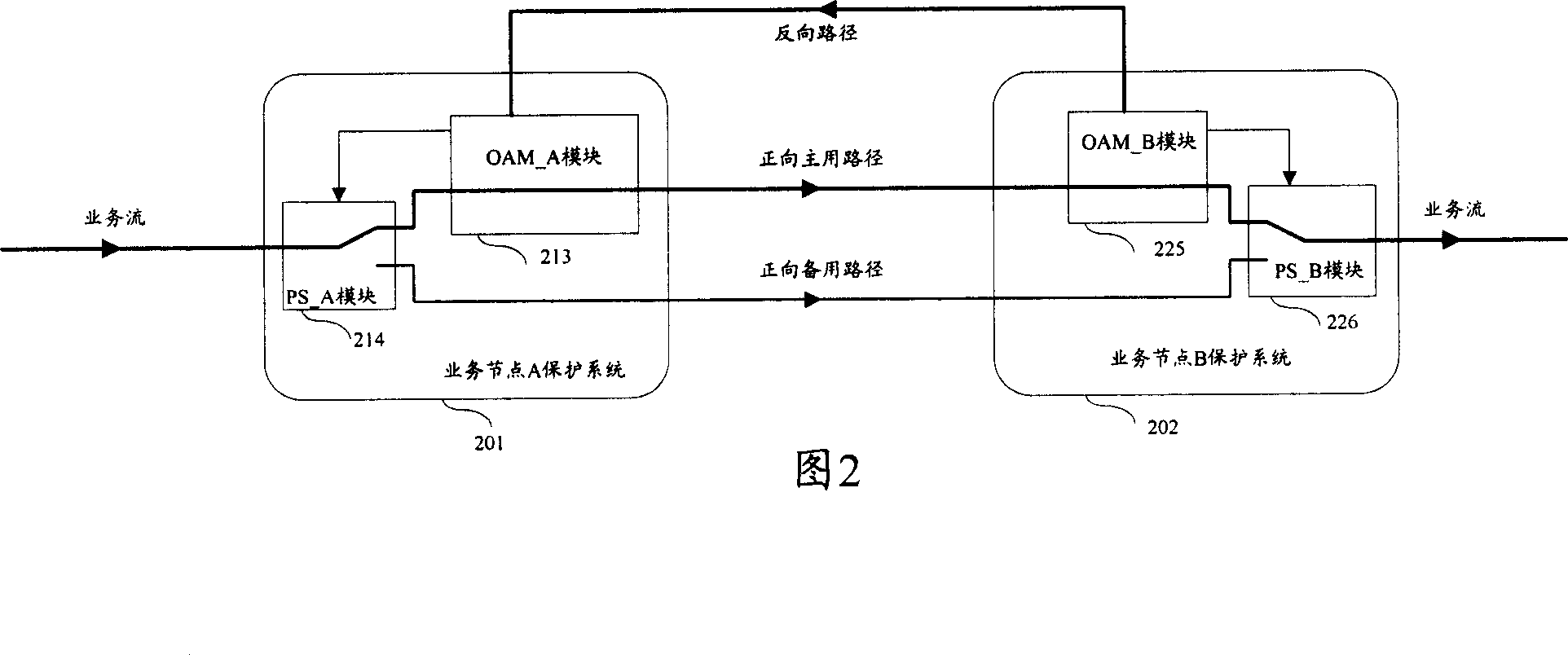
[0012] In practical application, the service flow protection method of the prior art is adopted. In the service flow protection system, only the forward path adopts the protection group. When the forward working path fails, the service flow export port performs forward path protection switching to switch the service flow. to the forward protection path, and transmit BDI packets through the single-path reverse path to notify the service flow ingress to switch paths. However, since the reverse path has no protection group, once the reverse path fails, the service flow ingress will If the BDI message cannot be detected, the forward path protection switching cannot be performed to switch the service flow to the forward protection path, and the status of the service flow at the ingress port and the egress port are inconsistent, resulting in interruption of the service flow

Method used


Image

  • Business flow protection method
  • Business flow protection method
  • Business flow protection method

Examples


Embodiment 1

[0048] Figure 4 is a structural diagram of the service flow protection system in Embodiment 1 of the present invention. There are two reverse paths connected between service node A and service node B in this embodiment, and these two reverse paths form a 1+1 protection group , including: a reverse primary path as a reverse working path, represented by a thick solid line in FIG. 4 ; and a reverse backup path as a reverse protection path, represented by a thin solid line in FIG. 4 . Normally, BDI packets are transmitted over the reverse primary path and the reverse backup path at the same time.

[0049] The service flow protection system in this embodiment includes: a service node A protection system 201 and a service node B protection system 202, where service node A is a service flow entry port, and service node B is a service flow exit port. The service node A protection system includes: OAM_A module 213, PS_A module 214 and PS_A_R module 414, PS_A_R module 414 is used to per...

Embodiment 2

[0061] Fig. 6 is the structural diagram of the service flow protection system of the second embodiment of the present invention. There are two reverse paths connected between the service node A and the service node B in this embodiment, and these two reverse paths form a 1:1 protection group , including: a reverse primary path as a reverse working path, represented by a thick solid line in FIG. 6 ; and a reverse backup path as a reverse protection path, represented by a thin solid line in FIG. 6 . Normally, BDI packets are transmitted on the reverse primary path.

[0062] The service flow protection system in this embodiment includes: a service node A protection system 201 and a service node B protection system 202, where service node A is a service flow entry port, and service node B is a service flow exit port. Service node A protection system includes: OAM_A module 213, PS_A module 214 and PS_A_R module 414; service node B protection system includes: OAM_B module 225, PS_B ...


PUM


Abstract

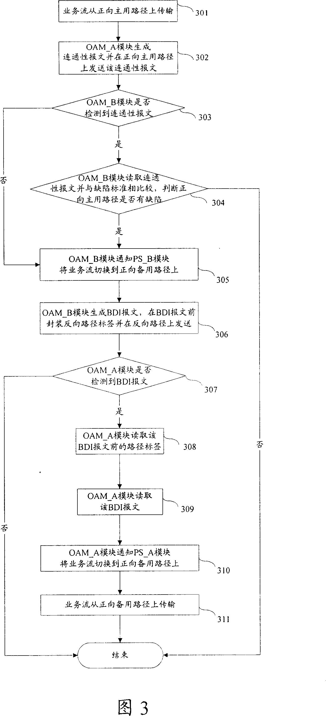
This invention discloses one business protection method, which adopts one to one protection set between two points positive path and comprises the following steps: a, business flow end point judges positive path shortcoming according to connection test results, if there is, then executing local point protection switching to generate BDI message at business flow mouth point and to send BDI message to business flow end point; b, business flow end points receive BDI message and executing local point switching.

Description

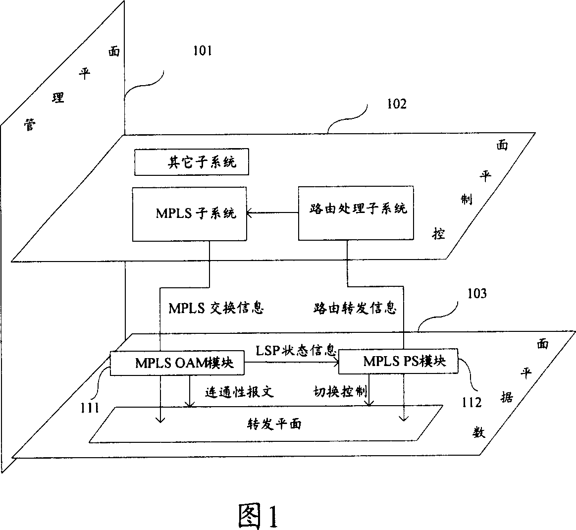
technical field [0001] The invention relates to a service flow protection technology, in particular to a service flow and protocol message protection method on a Multi-Protocol Label Switching (MPLS, Multi-Protocol Label Switching) network. Background technique [0002] Operation and Maintenance (OAM, Operations and Maintenance) and Protection Switching (PS, ProtectionSwitching) protocols are usually run on the Label Switching Path (LSP, Label Switching Path) in the current MPLS network to perform LSP connectivity detection, fault transfer and protection switching, In order to realize the protection of business flow. [0003] FIG. 1 is a structural diagram of an MPLS network device running OAM and PS protocols. The MPLS network device running OAM and PS protocols consists of a management plane 101 , a control plane 102 and a data plane 103 . Among them, the control plane 102 mainly completes call control, connection control, and protocol processing such as routing and signa...

Claims


Application Information

Patent Timeline
IPC IPC(8): H04L12/24H04L12/28
Inventor 张义龙
Owner JIANGSU HENGYUAN METAL MATERIALS
Learn More