Single-core inserted optical fiber cold connection extender

A cold connection and plug-in technology, which is applied in the field of single-core plug-in optical fiber cold connection and connection, can solve the problems of overall cost increase, resource waste, and high precision injection molding of mother and daughter, and achieve low manufacturing cost and high reliability. Effect

Inactive Publication Date: 2007-02-28
JIANGSU UNIKIT OPTICAL TECH
View PDF0 Cites 7 Cited by
  • Summary
  • Abstract
  • Description
  • Claims
  • Application Information

AI Technical Summary

Problems solved by technology

[0002] At present, in the field of optical fiber docking, the most famous is the Fibrlok optical fiber cold connector of 3M in the United States. The optical fiber through hole is formed in the middle, and there is a through groove on the wall of the metal cavity. The protruding ribs on the back of the mother body pass through the through groove and are higher than the metal shell. The optical fiber is stripped and cut, and pushed into the through hole, and then the steel wire is pulled out to tighten the copper spring sleeve, and the force is transmitted into the mother body through the back rib of the mother body, so that the optical fiber is fixed in the circular groove, so as to realize the docking; the scheme is in No axial thrust is provided to the optical fiber in the cold butt joint of the optical fiber, and the reliable and constant micro-feeding of the optical fiber axis cannot be achieved, which limits the success rate of the optical fiber connection; It cannot be reused, resulting in a waste of resources; in addition, because the structure has extremely high requirements on the injection molding precision of the mother and daughter bodies, the manufacturing cost of the whole set of devices is high, and the price of a single piece is more than 90 yuan; during the construction, the cutting surface of the optical fiber cannot always be used. Requirements, multiple joint adjustments and re-docking are required, which increases the labor load of construction personnel and increases the overall cost

Method used


Image

  • Single-core inserted optical fiber cold connection extender
  • Single-core inserted optical fiber cold connection extender
  • Single-core inserted optical fiber cold connection extender

Examples


Embodiment Construction

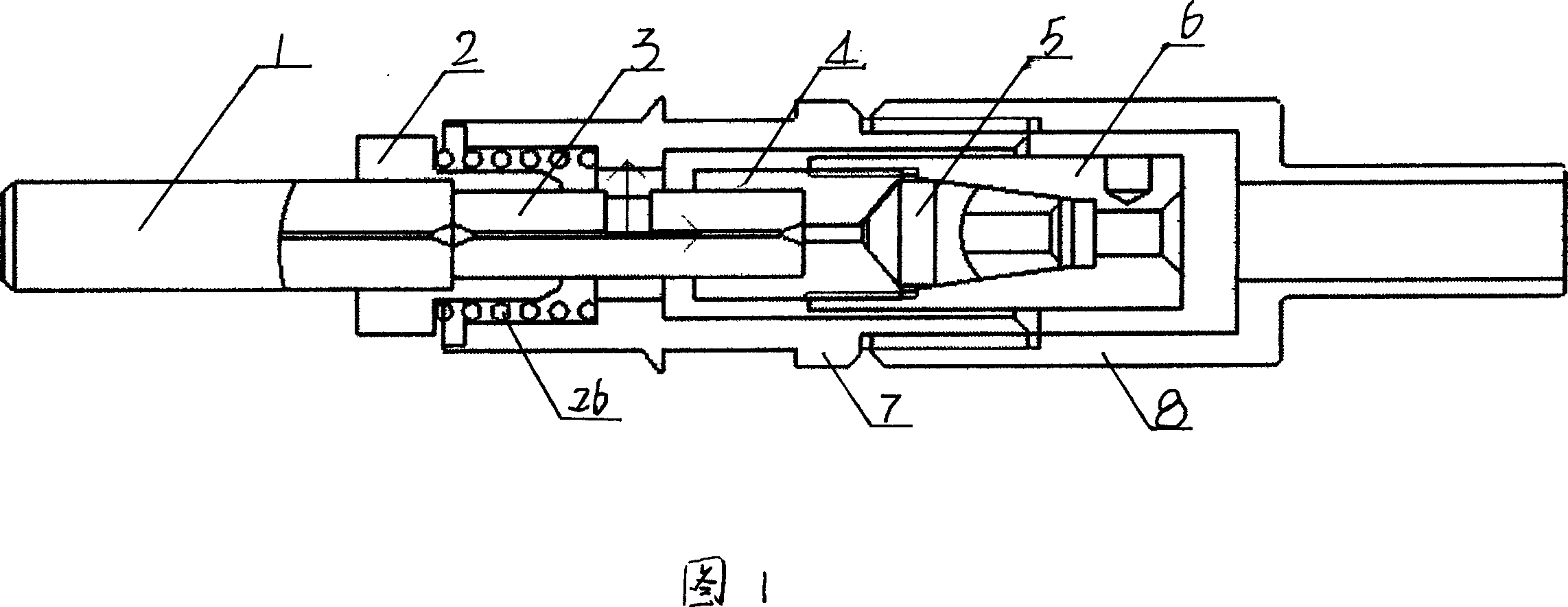
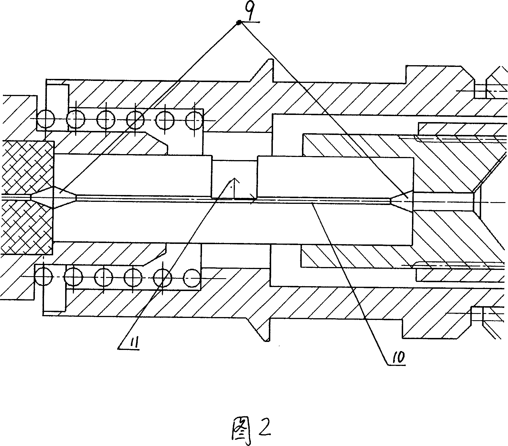
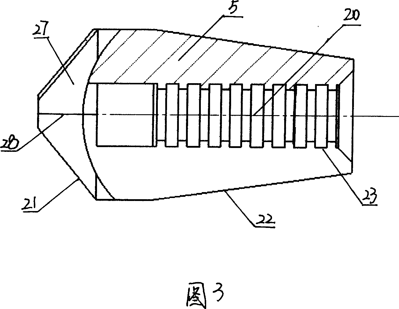
[0017] As shown in Figures 1 and 6, the cavity screw 7 is connected to the cavity nut 8 through the installation nut pair 25 to form an installation cavity 24, and the cold connection splicer body is installed in the installation cavity 24 to form an optical fiber cold connection splice as a whole; The connecting sub-body is mainly composed of a connecting device and a locking device, wherein the connecting device is composed of a pin 1, a connecting body 2, and a positioning body 3, and the pin 1 is connected to the positioning body 3 through a connecting body 2 to form a connecting device, wherein the locking The tightening device is composed of locking screw 4, locking nut 6 and double cone collet 5. The locking screw 4 is connected with the locking nut 6 through the locking nut pair 16 to form a locking cavity 12, and a double cone is installed in the locking cavity 12. The cone chuck 5 forms a locking device; wherein, as shown in Figure 2, the positioning body 3 is provide...


PUM


Abstract

The invention relates to a single-core insertion fiber cold connector, wherein the chamber screw (7) is connected to the chamber nut (8) to form mounting chamber (24); the mounting chamber (24) is mounted with cold connector to form fiber cold connector; the insert needle (1) via connector (2) is connected to the positioning element to form connecting device; the locking screw (4) is connected to the locking nut (6) to form locking chamber (12); the locking chamber (12) is mounted with dual-cone clamper (5) to form locking device; the connecting device via connector (2) is mounted at one end of chamber screw (7); another end of positioning element (3) is connected to one end of locking screw (4) that the cold connector formed by connector and locking device is mounted in mounting chamber (24) to form fiber cold connector. The invention uses accurate positioning and cone clamping to realize micro feeding, reduce cost and improve connecting success.

Description

technical field [0001] The invention relates to a connection device, in particular to a single-core plug-in optical fiber cold connection connector, which is a simple, convenient connection device that can realize reliable butt joint of optical fibers without any special device. Background technique [0002] At present, in the field of optical fiber docking, the most famous is the Fibrlok optical fiber cold connector of 3M in the United States. The optical fiber through hole is formed in the middle, and there is a through groove on the wall of the metal cavity. The protruding ribs on the back of the mother body pass through the through groove and are higher than the metal shell. The optical fiber is stripped and cut, and pushed into the through hole, and then the steel wire is pulled out to tighten the copper spring sleeve, and the force is transmitted into the mother body through the back rib of the mother body, so that the optical fiber is fixed in the circular groove, so ...

Claims


Application Information

Patent Timeline
Patent Type & Authority Applications(China)
IPC IPC(8): G02B6/36
Inventor 吕根良
Owner JIANGSU UNIKIT OPTICAL TECH
Why Eureka
Try Eureka