
Headlamp for vehicle

一种前照灯、车辆的技术,应用在车辆照明系统、车头灯、道路车辆等方向,能够解决恶化、易变为高温等问题,达到缩短前后长度、实现结构紧凑化、增加利用光束的效果

Active Publication Date: 2007-02-28
KOITO MFG CO LTD
View PDF2 Cites 19 Cited by
  • Summary
  • Abstract
  • Description
  • Claims
  • Application Information

AI Technical Summary

Problems solved by technology

[0009] However, when the surface shape of the reflection surface of the first additional reflection mirror is set to the shape of a spheroid as described above, the radiant heat from the light source is concentrated on the second focal point, and there is a second additional reflector near the second focal point. Reflectors are prone to high temperatures, and the undercoat layer of the vapor-deposited film that forms the reflective surface deteriorates early due to the influence of radiant heat from the light source

Method used


Image

  • Headlamp for vehicle
  • Headlamp for vehicle
  • Headlamp for vehicle

Examples


Embodiment Construction

[0078] Embodiments of the present invention will be described in detail below using the drawings.

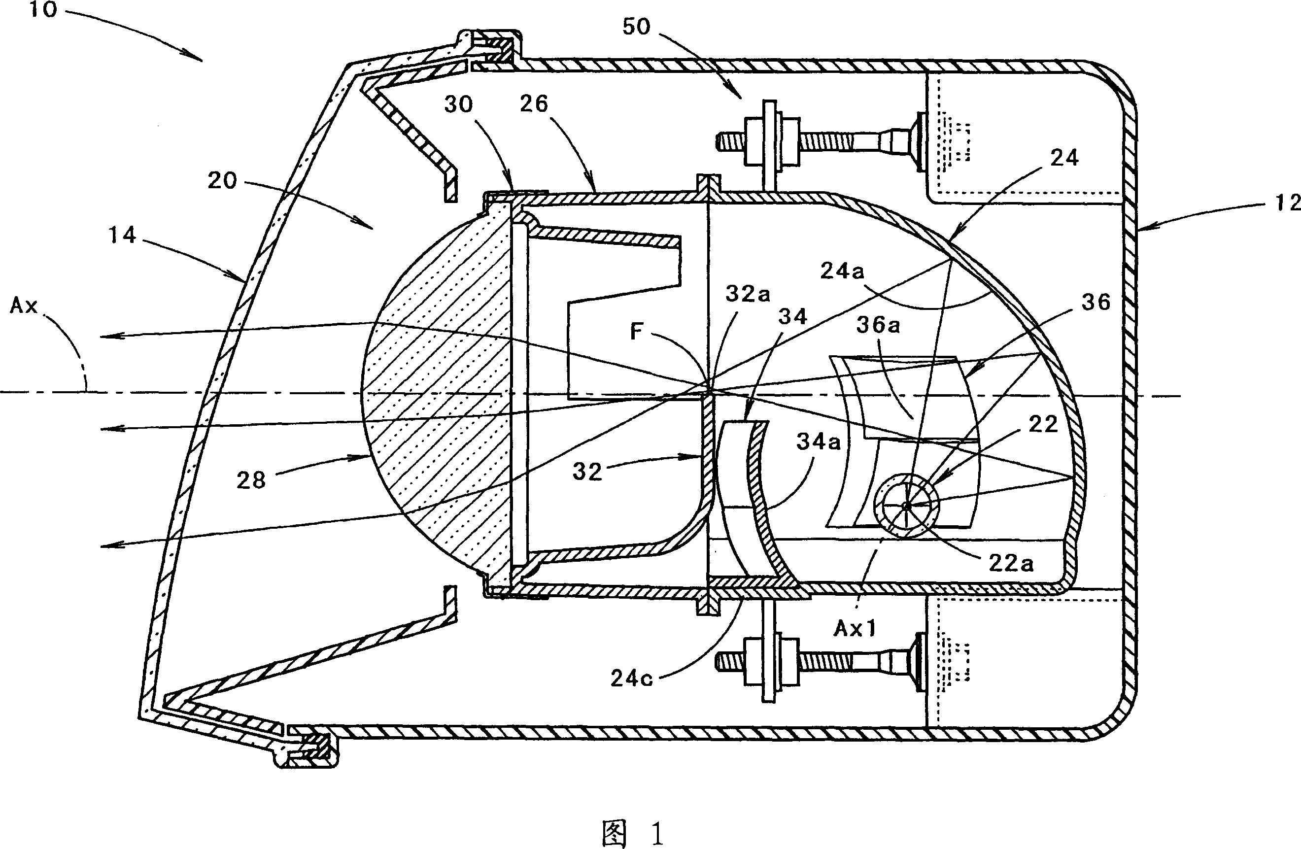
[0079] FIG. 1 is a side sectional view showing a vehicle headlamp 10 according to an embodiment of the present invention.

[0080] As shown in FIG. 1 , the vehicle headlight 10 is a vehicle headlight installed on the right front end of the vehicle, and the lamp unit 20 having an optical axis Ax extending in the front-rear direction of the vehicle can be moved up and down by an alignment mechanism 50 . It is accommodated in a lamp chamber formed by a lamp body 12 and a transparent light-transmitting cover 14 mounted on the front end opening thereof so as to be tilted in the direction and left and right directions.

[0081] At a stage after the alignment adjustment by the alignment mechanism 50 is completed, the optical axis Ax of the lamp unit 20 extends in a downward direction of about 0.5-0.6° with respect to the vehicle front-rear direction.

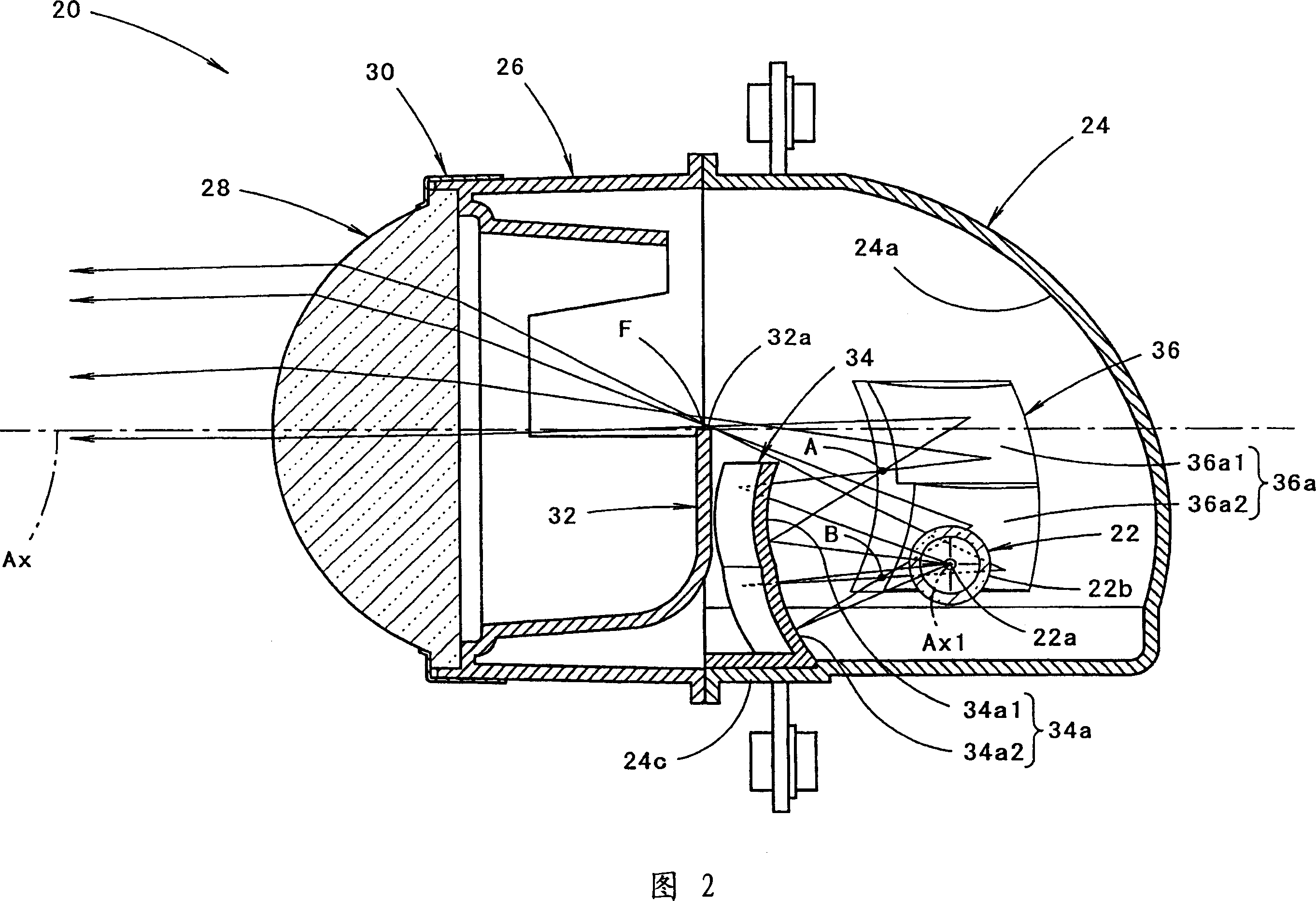
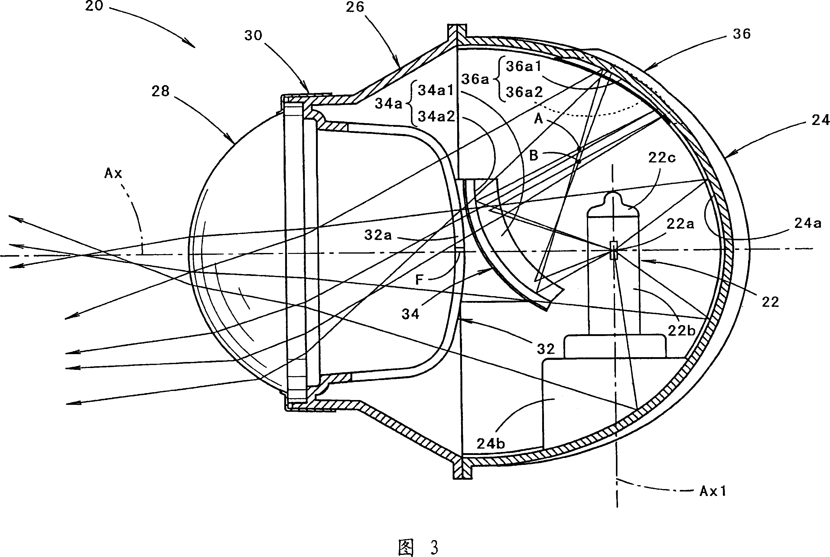
[0082] 2 and 3 are side sectiona...


PUM


Abstract

A vehicle headlamp. In the projection type vehicle headlamp, even if a side insertion type lamp structure is adopted, in addition to effectively suppressing the thermal impact on the structural components of the lamp, it can also form a sufficiently bright Light distribution pattern for low beam. A first additional reflector (22) is provided between the light source bulb (22) and the light shielding member (32) to reflect the light from the light source (22a) toward the area in front of the bulb insertion direction on the reflective surface (24a) of the reflector (24). 34), the area in front of the bulb insertion direction constitutes a second additional reflector (36) that causes the light reflected by the first additional reflector to move forward and reflect near the optical axis (Ax). The reflective surfaces (34a, 36a) of each additional reflector are divided into upper-stage reflection parts (34a1, 36a1) and lower-stage reflection parts (34a2, 36a2). The second focal points (A, B) of the rotational ellipse constituting the surface shape of the upper reflective portion (34a1) and the lower reflective portion (34a2) are separated vertically, so that the radiant heat from the light source is not concentrated at one point.

Description

technical field [0001] The present invention relates to a so-called projection type vehicle headlamp, and more particularly to a vehicle headlamp configured to form a low beam light distribution pattern. Background technique [0002] In general, a projection type vehicle headlamp is configured by disposing a projection lens on an optical axis extending in the front-rear direction of the vehicle, and disposing a light source at a position rearward from its rear focal point, so that light from the The light from the light source is reflected by the reflector near the optical axis. At this time, in the vehicle headlamp for low beam, part of the reflected light from the reflector is shielded by the shade provided with the upper edge near the rear focal point of the projection lens. [0003] In Patent Document 1, a so-called side-inserted lamp structure is described in such a projection-type vehicle headlamp. A line-segment light source extending axially around the bulb. [00...

Claims


Application Information

Patent Timeline
Patent Type & Authority Applications(China)
IPC IPC(8): F21S8/10F21V13/12F21W101/02F21W107/10F21Y101/00
CPCF21S48/1364F21S48/1388F21S41/168F21S41/17F21S41/255F21S41/321F21S41/365F21S41/43F21S41/335
Inventor 木下雅夫
Owner KOITO MFG CO LTD
Learn More