Eureka AIR delivers breakthrough ideas for toughest innovation challenges, trusted by R&D personnel around the world.

IGBT drive, and process method for driving signal

A driver and signal technology, applied in the direction of semiconductor devices, electrical components, transistors, etc., can solve the problems of uncommon application, high cost, complicated circuit, etc., and achieve the effect of simplified control circuit, small package and simple circuit

Inactive Publication Date: 2007-02-21
MORNSUN GUANGZHOU SCI & TECH
View PDF1 Cites 23 Cited by
  • Summary
  • Abstract
  • Description
  • Claims
  • Application Information

AI Technical Summary

Problems solved by technology

The cost of this method is relatively high, the circuit is relatively complicated, and the application is not common

Method used


Image

  • IGBT drive, and process method for driving signal
  • IGBT drive, and process method for driving signal
  • IGBT drive, and process method for driving signal

Examples


Embodiment Construction

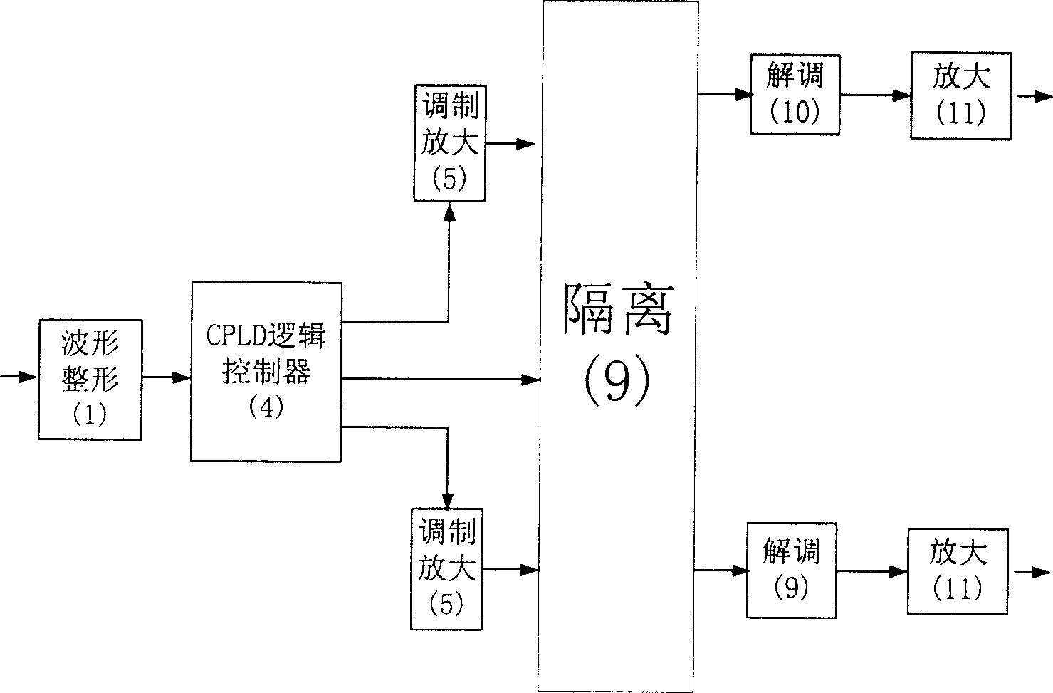
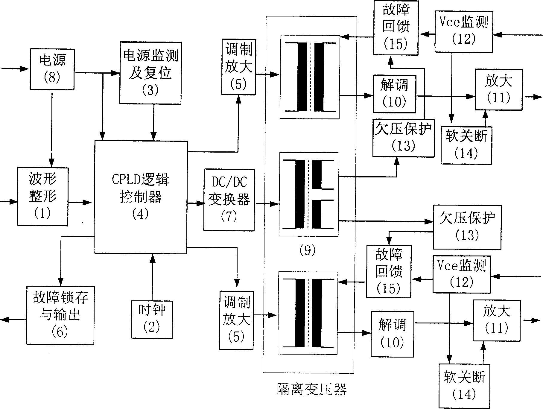
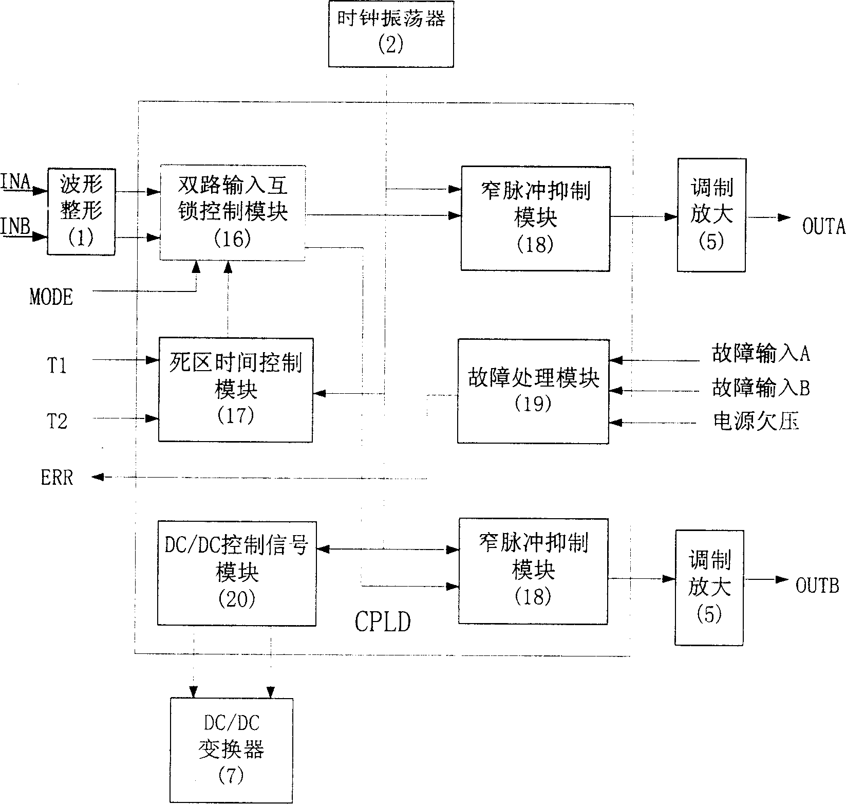
[0029] Such as figure 1 As shown, an IGBT driver provided by the present invention includes a waveform shaping circuit for converting an input signal into a rectangular wave, a CPLD logic controller for completing complex logic processing on the signal, and a pulse modulation amplification circuit for converting a sharp pulse signal The circuit is used to couple the signal to the secondary isolation transformer, and is used to restore the pulse demodulation circuit and output amplifier circuit of the PWM pulse signal; the input PWM signal first passes through the waveform shaping circuit and becomes a rectangular wave with a steep edge, a rectangular wave The wave signal is input to the CPLD logic controller to complete the logic processing of the signal. The output pulse control signal enters the modulation amplifier circuit, and the spike pulse signal generated is coupled to the secondary through the isolation transformer, and then restored to the PWM pulse signal by the demo...


PUM


Abstract

The invention comprises a shaping circuit, a CPLD logic controller, a pulse modulation amplification circuit, an isolating transformer, a pulse demodulation circuit and an output amplification circuit. The inputted signals are translated into the square wave through the shaping circuit, and then are inputted into the CPLD logic controller to make logic process; after outputting, the signals pass through the modulation amplification circuit to generate the sharp pulse signals that are coupled to the sublevel through the isolating transformer and reduced to PWM signals through the demodulation circuit; finally, driving the IGBT through the output amplification circuit.

Description

technical field [0001] The invention relates to an insulated gate bipolar transistor (IGBT) driver, in particular to an IGBT driver using a programmable logic device (CPLD) as a processing circuit. In addition, the present invention also relates to a processing method of the driving signal in the above-mentioned driver. Background technique [0002] Because the insulated gate bipolar transistor (IGBT) has the characteristics of high current capacity and voltage capacity, small conduction loss, and low static driving power, it is widely used in medium and high power converters. The function of the IGBT driving circuit is to convert the switching signal from the microcontroller into a driving pulse signal with sufficient power to ensure that the IGBT is turned off and turned on reliably. At the same time, the IGBT drive circuit also provides safe electrical isolation for the voltage between the microcontroller and the power transistors. In order to get correct and effective ...

Claims


Application Information

Patent Timeline
Patent Type & Authority Applications(China)
IPC IPC(8): H03K17/04H03K17/08H03K17/06H03K17/60
Inventor 尹向阳张黎
Owner MORNSUN GUANGZHOU SCI & TECH
Why Eureka
Eureka Blog
Learn More