Optically ignited spark gap

A spark gap and trigger signal technology, which is applied to spark gaps with auxiliary trigger devices, spark gaps, spark gap parts, etc., can solve problems such as troublesome maintenance and huge costs

Inactive Publication Date: 2010-06-23
SIEMENS AG
View PDF5 Cites 0 Cited by
  • Summary
  • Abstract
  • Description
  • Claims
  • Application Information

AI Technical Summary

Problems solved by technology

[0009] Known overvoltage protection devices are expensive and maintenance-intensive due to the required circuitry with power supply on the platform

Method used


Image

  • Optically ignited spark gap
  • Optically ignited spark gap
  • Optically ignited spark gap

Examples


Embodiment Construction

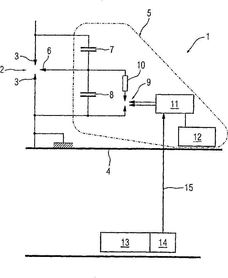
[0026] FIG. 1 shows a known embodiment of an overvoltage protection device 1 according to the prior art, which has already been described above.

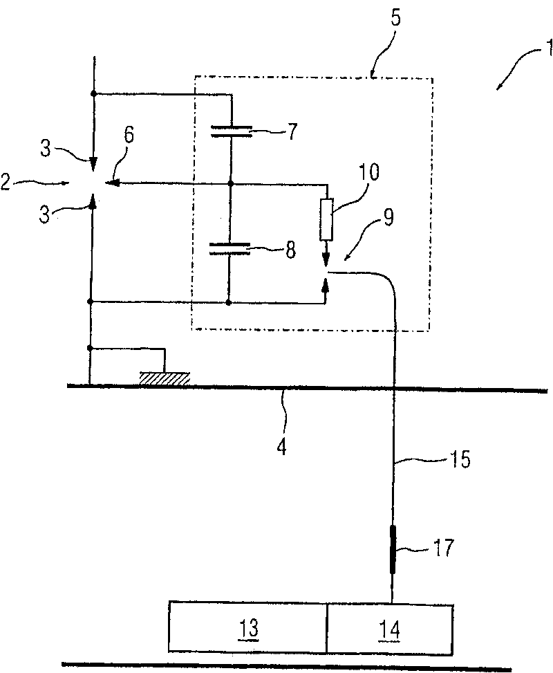
[0027] figure 2 An embodiment of the overvoltage protection device 1 according to the invention is shown, which is connected in parallel to components not shown in the figure, such as high-voltage capacitors, which are arranged on the platform 4 . Here, high-voltage capacitors are connected in series in one phase of the high-voltage AC grid. In order to avoid higher potential differences, components that can be coupled to the high-voltage lines of the AC network are arranged on a platform 4, for example on a support made of ceramic, thermoplastic synthetic resin, etc., in an environment at ground potential Keep it insulated.

[0028]In the illustrated embodiment, the overvoltage protection device 1 comprises a main spark gap 2 formed by a main electrode 3 , which can be triggered by means of a trigger electrode 6 . A trigger circ...


PUM


Abstract

The invention relates to an overvoltage protector (1) comprising a spark gap (2) with opposing electrodes (3) and a light source for generating an ignition light in accordance with the trigger signals of a control unit, said ignition light being configured to directly ignite the spark gap (2). The aim of the invention, is to facilitate a reliable ignition of the spark gap. To achieve this, the overvoltage protector is equipped with an optical fibre (15) for conducting the ignition light to the spark gap (2).

Description

technical field [0001] The invention relates to an overvoltage protection device comprising: a spark gap with electrodes arranged opposite to each other, a light source for generating trigger light according to a trigger signal from a control unit, wherein the trigger light is used for directly triggering the spark gap. Background technique [0002] DE 19718660 A1 already discloses such an overvoltage protection device. The overvoltage protection device described therein has a spark gap consisting of two electrodes facing each other. To trigger the spark gap, a pulsed nitrogen laser is provided, whose laser pulses in the UV (ultraviolet) range are deflected in a gas chamber delimited by electrodes. In order to couple the triggering light into the spark gap surrounded by the housing, a window made of quartz glass is provided which is transparent to UV light. To reduce the energy of the light pulse required to trigger the spark gap, metal aerosols are placed between the elec...

Claims


Application Information

Patent Timeline
Patent Type & Authority Patents(China)
IPC IPC(8): H01T1/20H01T2/00H01T2/02H02H1/00H02H9/06
CPCH01T2/00H02H1/0069H02H9/06H01T1/20H01T2/02
Inventor 彼得·门克
Owner SIEMENS AG
Why Eureka
Try Eureka