
Optical therapeutic device

A technology of phototherapy device and light-transmitting cover, applied in the field of phototherapy device, can solve problems such as inability to adjust differently, dryness, skin loss of moisture, etc.

Inactive Publication Date: 2007-01-24
徐福裕 +2
View PDF0 Cites 6 Cited by
  • Summary
  • Abstract
  • Description
  • Claims
  • Application Information

AI Technical Summary

Problems solved by technology

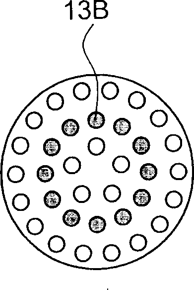
But, this phototherapy device 10, several light-emitting diodes 13 on it are arranged in a ring, although it can be according to different irradiation intensity, as Figure 2A As shown, select the outer ring light-emitting diode (LED) 13A, or as Figure 2B As shown, the middle ring light-emitting diode (LED) 13B can also be as Figure 2C As shown, select any ring of the inner ring light-emitting diode (LED) 13C to use; the light-emitting diodes (LEDs) arranged in a ring, unless all the LEDs of each ring are turned on, otherwise the illuminated areas form circles of different sizes Annular aperture, rather than the uniform irradiation light waves of the entire irradiation head 12; therefore, it is easy to have the lack of irradiation dead angle
In addition, most of the existing LEDs 13A, 13B, and 13C are made of the same wavelength, and cannot be adjusted according to human skin quality or treatment parts, which is also one of its shortcomings.
Furthermore, when the existing phototherapy device is irradiated, because it produces more positive ions, it is easy to make the skin lose moisture and present a drier situation, which needs to be improved.

Method used


Image

  • Optical therapeutic device
  • Optical therapeutic device
  • Optical therapeutic device

Examples


Embodiment Construction

[0041] refer to image 3 and Figure 4As shown in the front view and side view of the structure of the present invention, its structure mainly includes: a housing 20, which is a shape that can be held by hand, and an accommodating chamber 21 is formed therein; an irradiation head 30 is located in the housing 20 , its preferred embodiment is integrally formed with the housing 20 , but it is not limited thereto, that is, it can be formed separately and then combined with the housing 20 . The irradiation head 30 is equipped with a light-transmitting cover 31, which can be installed from the inside to the outside of the irradiation head 30, but is not limited thereto, that is, it can be nested in the irradiation head 30 from the outside, or can be processed by high frequency or the like. The method is to fix it on the irradiation head 30, so it will not be described in detail.

[0042] Several LEDs 40 are electrically connected to a circuit board 50 , and the circuit board 50 is...


PUM


Abstract

The phototherapeutic device includes one casing with inside holding chamber and in the shape suitable for hand to hole; one irradiating head on the casing and with transparent cover; one circuit board with electrically connected LED's to emit light of at least two different wavelengths towards the transparent cover; one LED controlling circuit for powering the circuit board and driving the LED's; and one operating interface on the casing for selecting the on-off of the LED's to emit light of different wavelengths. The present invention can switch in different irradiation wavelengths for reaching different functions.

Description

1. Technical field [0001] The invention relates to physiotherapy equipment, in particular to a phototherapy device capable of switching different irradiation wavelengths according to different requirements, and the irradiation area strives to be uniformly distributed to reduce irradiation dead angles. 2. Background technology [0002] With the change of life style, people often have various lesions on the skin due to the factors of work pressure or eating habits. Therefore, in recent years, it has become a trend to use pulsed light (Intense Pulsed Light, IPL) to treat various skin diseases. [0003] The research on pulsed light began in 1990. Its spectrum of action is quite broad, about 550nm to 1200nm wavelength light, including visible light and infrared range. Pulsed light has the high energy and wavelength of laser, but the wavelength includes a wider range. Due to skin tissue, There are various reactions to the absorption and scattering of different light waves. The pu...

Claims


Application Information

Patent Timeline
Patent Type & Authority Applications(China)
IPC IPC(8): A61N5/06
Inventor 徐福裕徐福寿徐福荣
Owner 徐福裕
Learn More