
Conductive contact holder, conductive contact unit and process for producing conductive contact holder

A retainer and conductivity technology, which is applied in the direction of electrical components, manufacturing measuring instruments, single semiconductor device testing, etc., can solve problems such as difficult to control the size of the retainer substrate 101, and achieve the effect of suppressing warpage and position deviation

Inactive Publication Date: 2011-06-15
NHK SPRING CO LTD
View PDF5 Cites 0 Cited by
  • Summary
  • Abstract
  • Description
  • Claims
  • Application Information

AI Technical Summary

Problems solved by technology

[0008] In addition, the conventional conductive contact unit has a problem that it is difficult to control the size of the opening formed on the holder substrate 101.

Method used


Image

  • Conductive contact holder, conductive contact unit and process for producing conductive contact holder
  • Conductive contact holder, conductive contact unit and process for producing conductive contact holder
  • Conductive contact holder, conductive contact unit and process for producing conductive contact holder

Examples


Embodiment Construction

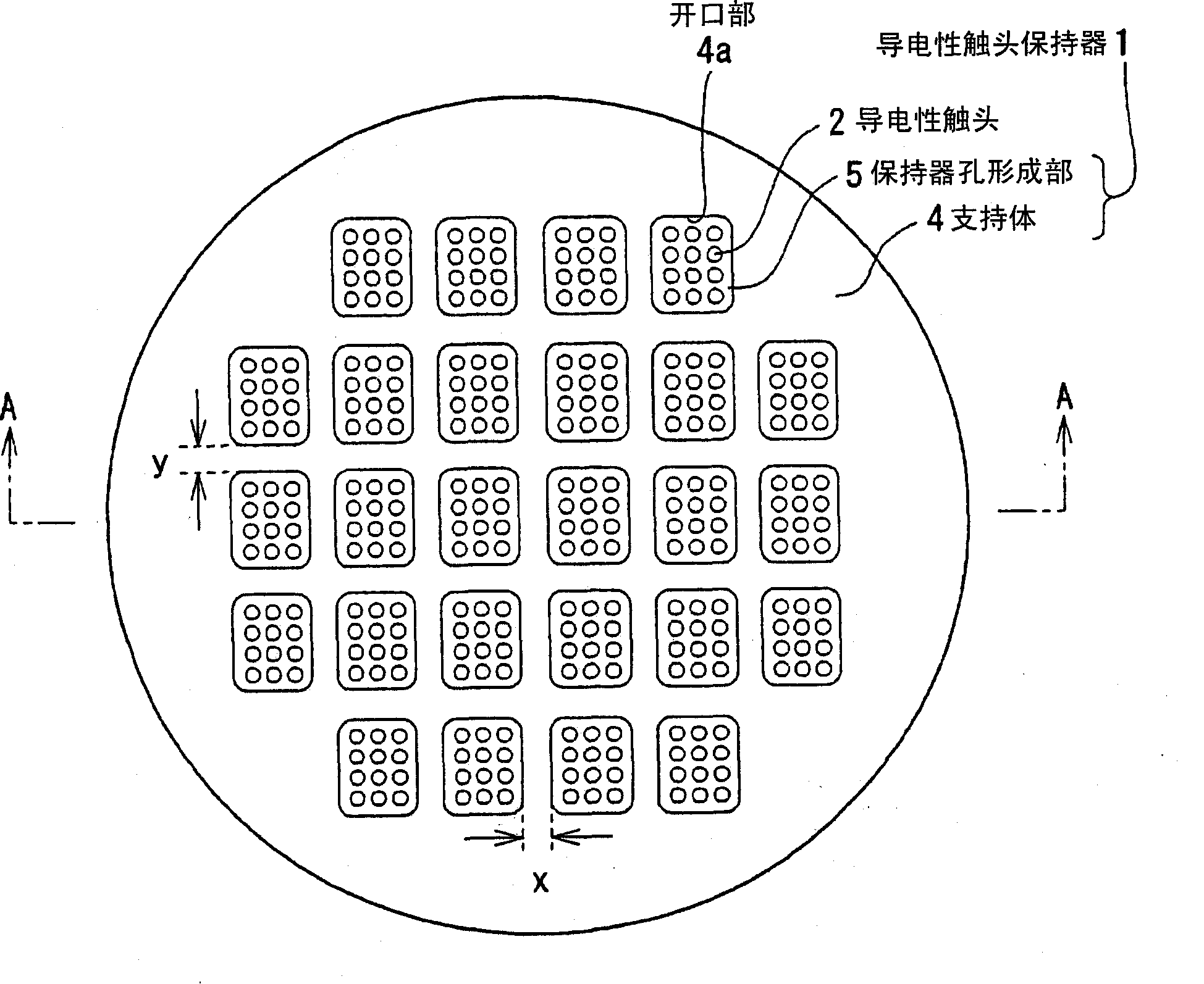
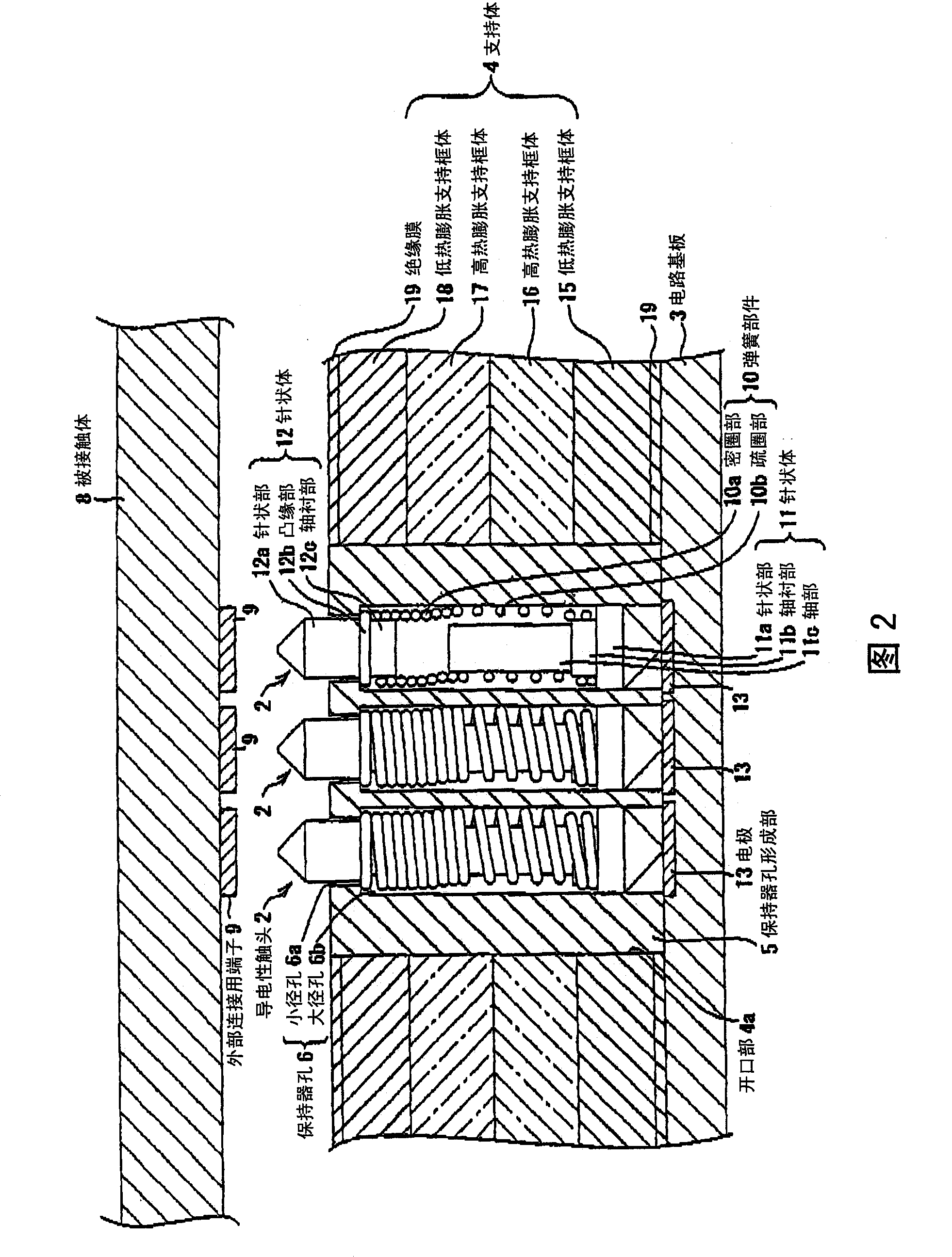
[0046] Hereinafter, the best mode for implementing a conductive contact unit to which the conductive contact holder of the present invention is applied (hereinafter referred to as "embodiment") will be described in detail with reference to the drawings. In addition, the drawings are schematic diagrams. It should be noted that the relationship between the thickness and width of each part, the ratio of the thickness of each part, etc. are different from the actual situation. Of course, the relationship or ratio of mutual dimensions is also included in the drawings. different parts.

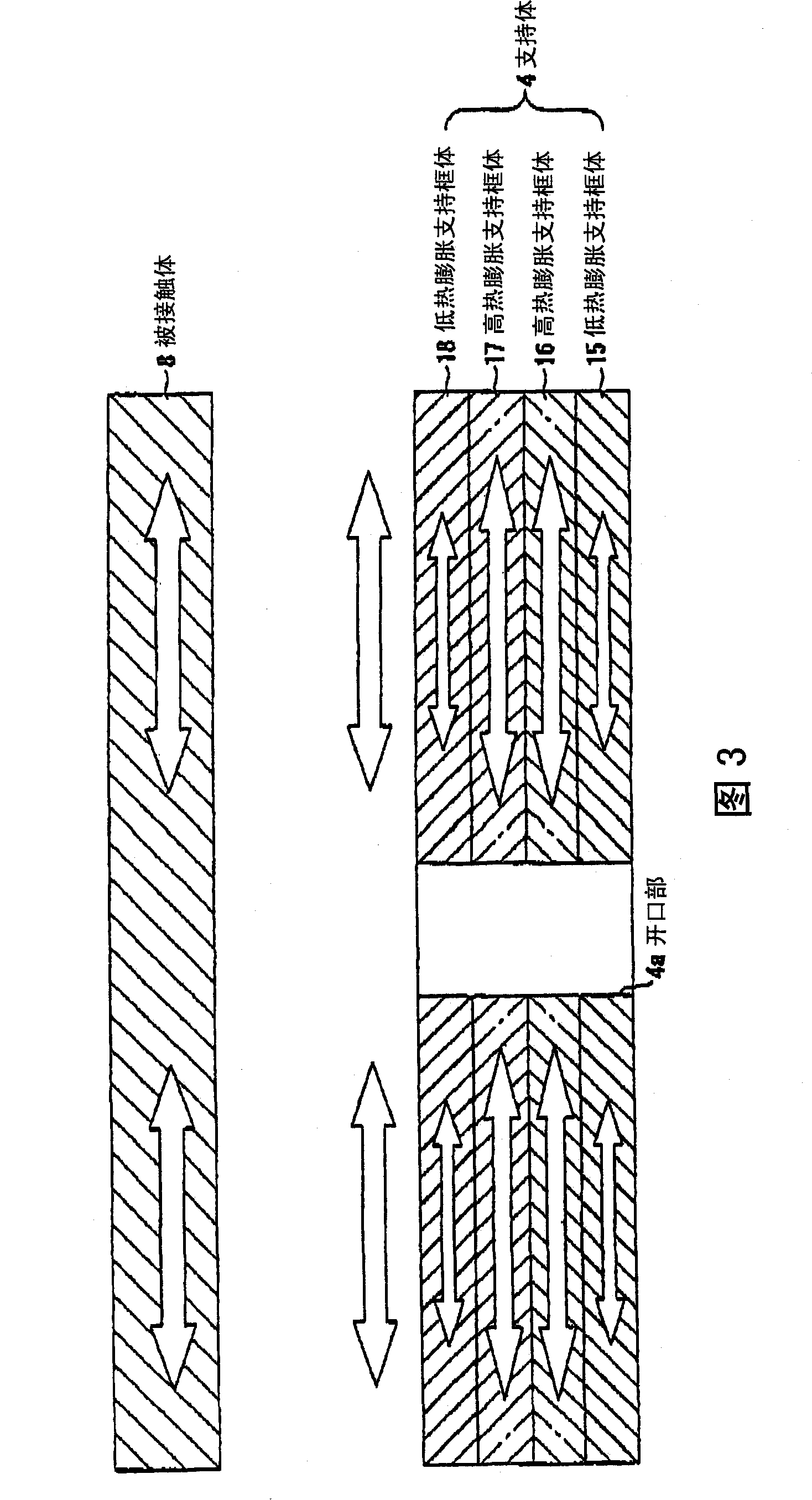
[0047] The conductive contact unit of the present embodiment has a structure that includes a support that supports a frame body with a high thermal expansion having a higher linear expansion coefficient than the contacted body, and has a lower linear expansion than the contacted body. Coefficients of low thermal expansion support frame stacks are obtained. figure 1 It is a plan view of the conduct...


PUM


Abstract

A support (4) for holding a conductive contact holder (1) has a structure of stacking low-thermal-expansion supporting frames (15, 18) having a linear expansion coefficient smaller than that of a body (8) to be touched, and high-thermal-expansion supporting frames (16, 17) having a linear expansion coefficient larger than that of the body (8) to be touched. With such a stack structure, linear expansion coefficients of the body (8) to be touched and the entire support (4) can be approximated, and positional deviation can be suppressed between a conductive contactor (2) and an external connection terminal (9) even under high temperature conditions.

Description

technical field [0001] The present invention relates to the technology described below, which is held by a support body, has a contact surface facing the terminal surface of the contacted body on which the terminal surface of the terminal for external connection is arranged, and accommodates a terminal corresponding to the terminal for external connection. A technology of a plurality of conductive contacts arranged on the contact surface and electrically connected to the external connection terminal. Background technique [0002] Conventionally, for the conductive contact unit used when inspecting the circuit structure of a semiconductor element formed on a silicon substrate, for example, a conductive contact unit for a semiconductor wafer with a diameter of about 200 mm has been proposed (for example, refer to Patent Document 1 ). Such a conductive contact unit has a structure in which conductive contacts are arranged corresponding to the arrangement pattern of terminals f...

Claims


Application Information

Patent Timeline
Patent Type & Authority Patents(China)
IPC IPC(8): G01R1/06G01R1/067G01R1/073H01L21/66G01R31/26G01R3/00
CPCG01R3/00G01R1/07314G01R31/2863G01R1/06722G01R1/06H01L22/00
Inventor 斋藤慎二风间俊男长屋光浩
Owner NHK SPRING CO LTD
Learn More