
Calibrated tester of oximeter

A test device and oximeter technology, applied in the calibration of instruments, instruments, instrument parts, etc., can solve the problems of difficult permanent stable reference standards, differences in tissue blood oxygen content, etc.

Inactive Publication Date: 2007-01-17
合肥安恒光电有限公司
View PDF0 Cites 4 Cited by
  • Summary
  • Abstract
  • Description
  • Claims
  • Application Information

AI Technical Summary

Problems solved by technology

Because different people or the same person in different states, the blood oxygen content of the tissue must be different, so it is difficult to use it as a permanent and stable reference standard

Method used


Image

  • Calibrated tester of oximeter
  • Calibrated tester of oximeter
  • Calibrated tester of oximeter

Examples


Embodiment 1

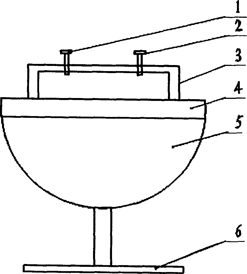
[0023] The oximeter calibration test device includes an integrating sphere 5, the bottom of which is connected to the base 6 to form a goblet shape. The integrating sphere 5 is a hemispherical shell with a diameter of 200 mm and a wall thickness of 2 mm processed from duralumin, and its inner surface is coated with Thickness is the polyester fluoroethylene material layer of 2 millimeters; The bottom disk diameter of base 6 is 120 millimeters, thickness 5 millimeters, and middle part connecting rod diameter is 15 millimeters, high 70 millimeters.

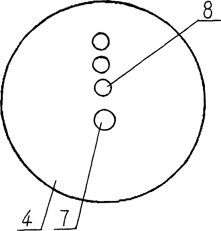
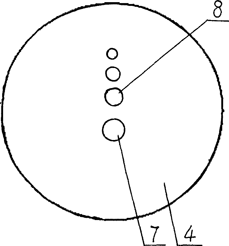
[0024] The upper opening of the integrating sphere 4 is a disc-shaped working platform 4, on the working platform 4, there are a transmitting hole 7 and three receiving holes 8 in sequence along the diameter direction; the transmitting hole diameter is 10 mm, and the diameter of the three receiving holes is equal to is 3mm. The center-to-center distance between the transmitting hole 7 and the adjacent receiving hole 8 is 20 mm, and t...

Embodiment 2

[0028] The diameter of the transmitting hole 7 is 12 millimeters, and the diameters of the three receiving holes 8 are respectively 5 millimeters, 1.65 millimeters, and 0.5 millimeters; the transmitting hole 7 is adjacent to the receiving hole 8 with a diameter of 5 millimeters, and the transmitting hole 7 is adjacent to the adjacent receiving hole 8 The distance between centers is 20 mm, and the distance between centers of adjacent receiving holes is 10 mm.

[0029] Others are with embodiment 1.


PUM

PropertyMeasurementUnit
Diameteraaaaaaaaaa
Thicknessaaaaaaaaaa
Diameteraaaaaaaaaa

Abstract

A calibration tester for oxyhemograph is composed of a base, an integration semi-sphere connected to base to form a high-leg wine cup's shape, and a disc-shaped working platform on the top of said integration semi-sphere and with one emitting hole and three receiving holes. It can provide a permanent and stable test standard for calibration and static test.

Description

technical field [0001] The invention relates to a calibration test device for an oximeter. Background technique [0002] In the manufacturing process of the oximeter, there are two important tasks to be completed, one is calibration and the other is static testing. [0003] Since the two transmitting tubes and the two receiving tubes on the detection head are on the same plane, the calibration is performed in a dark room, and the two transmitting tubes are emitted to a diffuse reflector such as a large-area reflective surface, a curtain or a flat and clean wall far away. The laser light forms a relatively evenly distributed diffuse reflection light, and the light intensity received by the two receiving tubes placed parallel to the direction of the wall is basically the same. The main disadvantage of this method is that it is not easy to form an ideal darkroom with a large space, and it is difficult to maintain stable optical properties for a long time with a large-area diff...

Claims


Application Information

Patent Timeline
IPC IPC(8): A61B5/1455G12B13/00
Inventor 过传良吴先友李岳
Owner 合肥安恒光电有限公司
Learn More