


Quick Research
Generate reliable direction feasibility study reports for your R&D in just a few steps.

Technical Q&A
Discover and master advanced knowledge NOW. Basics, ideas, possibilities, all at once.

Find Solutions
As an expert in R&D theories, this can generate solutions to your technical problems instantly.

Evaluate Feasibility
Analyze your overall solution with one click, know your potential R&D risks in advance.

Monitor Landscape
Get weekly tech updates, stay abreast of the latest tech innovations and key insights.
Constant-pressure water tank antifreezing solar water heater
A technology for water heaters and pressurized water tanks, which is applied to solar thermal devices, solar thermal power generation, heating devices, etc., can solve the problems of complex antifreeze structure, high failure rate, and high cost, so as to reduce system failure rate and manufacturing cost. The effect of simple structure
- Summary
- Abstract
- Description
- Claims
- Application Information
AI Technical Summary
Problems solved by technology
Method used
Image

Examples
Embodiment Construction
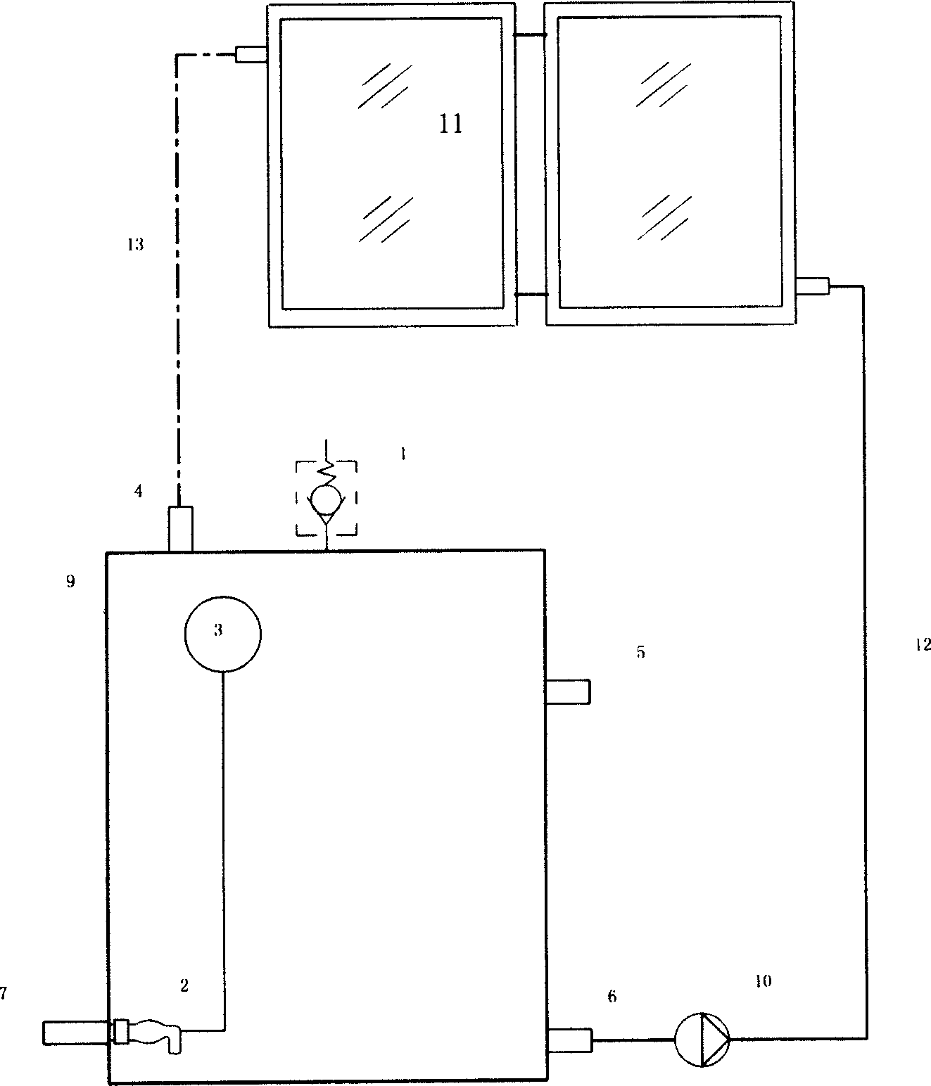
[0015] exist figure 1 In the illustrated embodiment:
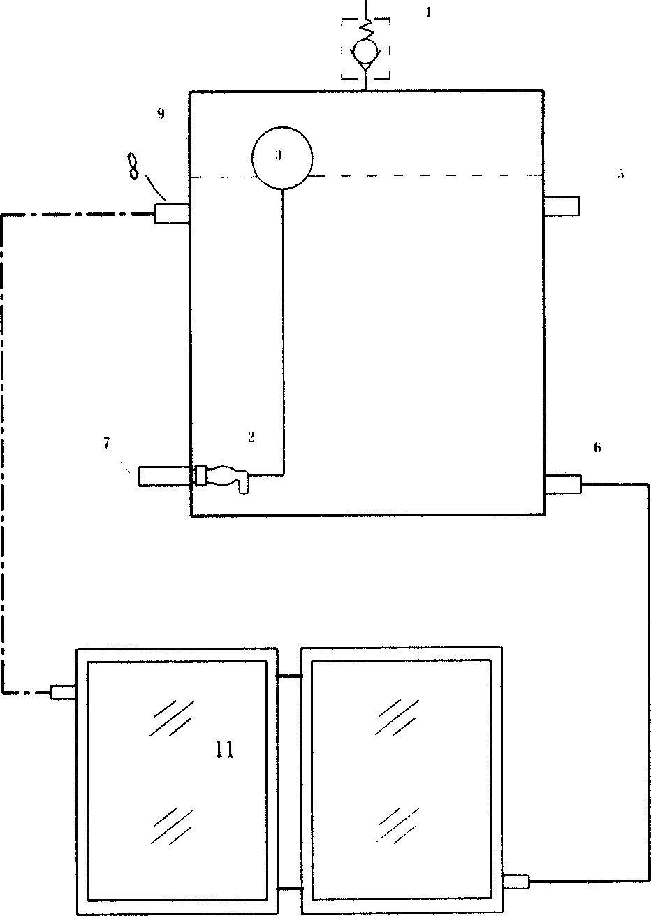
[0016] The closed water tank is equipped with a float valve and a pressure limiting valve to control the liquid level pressure in the closed water tank and keep it constant. When the system is forced to circulate, the cold water returns to the water tank from the cold circulation pipe through the heat collector and the heat circulation pipe. After the circulation stops , the water in the heat collector automatically flows into the water tank through the cold circulation pipe due to its own weight. At this time, the gas in the heat preservation water tank is automatically replenished into the heat collector and the circulation pipe through the heat circulation pipe. It will not be damaged by freezing (the inside of the collector is full of gas). exist figure 2 In the illustrated embodiment:
[0017] The closed water tank is equipped with a float valve and a pressure limiting valve to control the pressure in the closed w...
PUM
 Abstract
Description
Claims
Application Information
 - R&D Engineer
- R&D Manager
- IP Professional
- Industry Leading Data Capabilities
- Powerful AI technology
- Patent DNA Extraction
Browse by: Latest US Patents, China's latest patents, Technical Efficacy Thesaurus, Application Domain, Technology Topic, Popular Technical Reports.
© 2024 PatSnap. All rights reserved.Legal|Privacy policy|Modern Slavery Act Transparency Statement|Sitemap|About US| Contact US: help@patsnap.com