Breaker with water tank

A technology for circuit breakers and water tanks, applied in circuits, parts of protection switches, electrical components, etc., can solve the problems of poor heat dissipation performance of circuit breakers, inability to achieve heat dissipation effects, and unreasonable structural settings, so as to reduce quality and accident hazards. , Reduce various quality and accident hazards, good heat dissipation effect

Inactive Publication Date: 2016-08-24
吴娟香
View PDF7 Cites 0 Cited by
  • Summary
  • Abstract
  • Description
  • Claims
  • Application Information

AI Technical Summary

Problems solved by technology

[0002] The existing solid-state circuit breaker has a groove designed for heat dissipation on the end face of the shell, and the area of ​​the end face of the shell is relatively small, so the heat dissipation area is relatively small. More importantly, this design is suitable for a circuit breaker heat dissipation requirements, but the known circuit breakers are often spliced ​​together, and a large amount of heat will be generated on the spliced ​​surface. If the heat dissipation groove is set on the end face of the circuit breaker, the heat generated by the spliced ​​surface cannot The end face of the shell is effectively dissipated, and the effective heat dissipation effect cannot be achieved
On August 30, 2012, Jiangsu Zhongren Electric Co., Ltd. invented a method to solve the heat dissipation problem of circuit breakers, especially the heat dissipation problem caused by the splicing surface when multiple circuit breakers are spliced ​​together. Circuit breaker", Chinese patent authorization announcement number CN 202855587 U. In the technical solution of this patent, four cooling holes are set on the splicing surface. Once multiple circuit breakers are spliced, all the cooling holes will be covered, making the heat dissipation performance of the circuit breaker poor. , the structure setting is unreasonable

Method used


Image

  • Breaker with water tank
  • Breaker with water tank

Examples


Embodiment Construction

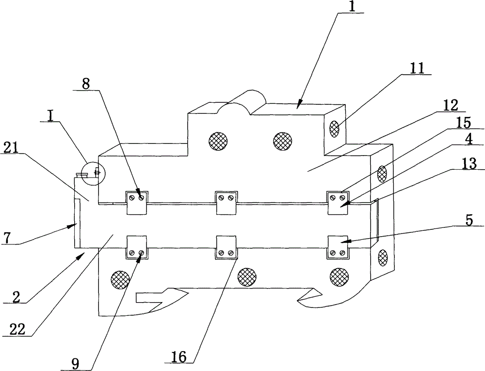
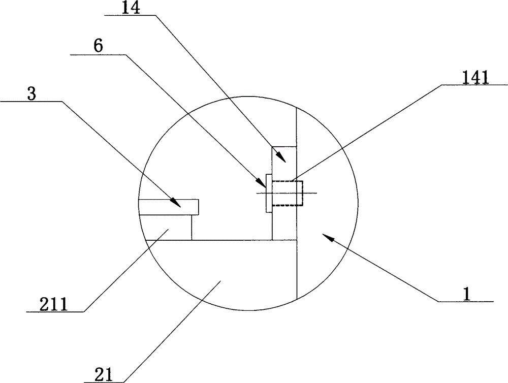
[0018] see figure 1 and figure 2 , a circuit breaker with a water tank disclosed in the present invention, comprising a housing 1, the housing 1 is provided with several heat dissipation holes 11, and the middle part of the splicing surface 12 of the housing 1 is provided with a heat dissipation groove 13, so A water tank 2 is arranged in the heat dissipation groove 13, and the water tank 2 includes a water filling part 21 and a heat dissipation part 22. The water filling part 21 and the heat dissipation part 22 together form an "L" shape structure, and the upper end of the water filling part 21 is provided with a water filling port. 211, the water inlet 211 is threadedly connected with a sealing nut 3, the upper end of the heat dissipation groove 13 is detachably provided with several water tank upper baffles 4, and the lower end of the heat dissipation groove 13 is detachably provided with several water tank lower baffles 5. The upper end of the water filling part 21 is in...


PUM


Abstract

The invention discloses a breaker with a water tank; the breaker comprises a housing provided with a plurality of radiation holes; a spliced face middle portion of the housing is provided with a radiation groove; the water tank is arranged in the radiation groove, and comprises a water adding portion and a radiation portion combined to form an L shaped structure; a top of the water adding portion is provided with a water adding port screwed with a sealed screw nut; a top of the radiation groove is detachably provided with a plurality of water tank upper stop plates; a bottom of the radiation groove is detachably provided with a plurality of water tank lower stop plates; the top, close to the housing, of the water adding portion is provided with a boss; the boss is provided with a connecting hole penetrated by a first connecting screw; and the water adding portion uses the first connecting screw to fix the boss with the housing. The water is added to the water tank, so the breaker is good in heat adsorption and radiation performance, and the heat generated by the breaker spliced face can be fast released to the environment.

Description

technical field [0001] The invention relates to the technical field of circuit breakers, in particular to a circuit breaker with a water tank. Background technique [0002] The existing solid-state circuit breaker has a groove designed for heat dissipation on the end face of the housing, and the area of ​​the end face of the housing is relatively small, so the heat dissipation area is relatively small. More importantly, this design is suitable for a circuit breaker heat dissipation requirements, but the known circuit breakers are often spliced ​​together and used, and the inevitable splicing surface will generate a lot of heat. If the heat dissipation groove is set on the end face of the circuit breaker, the heat generated by the splicing surface cannot The end face of the shell is effectively dissipated, and an effective heat dissipation effect cannot be achieved. On August 30, 2012, Jiangsu Zhongren Electric Co., Ltd. invented a method to solve the heat dissipation proble...

Claims


Application Information

Patent Timeline
IPC IPC(8): H01H9/52H01H71/02
Inventor 吴娟香
Owner 吴娟香
Why Eureka
Try Eureka